background image


Technical documentation 


Subject to modifications 


47 of 131 


4.4.12. Installation diagram 

The installation of the plant is carried out in accordance with Hoval's specifications. 
All plant and electrical supply lines must be placed and installed in accordance with the 
installation plan or Hoval's specifications. 

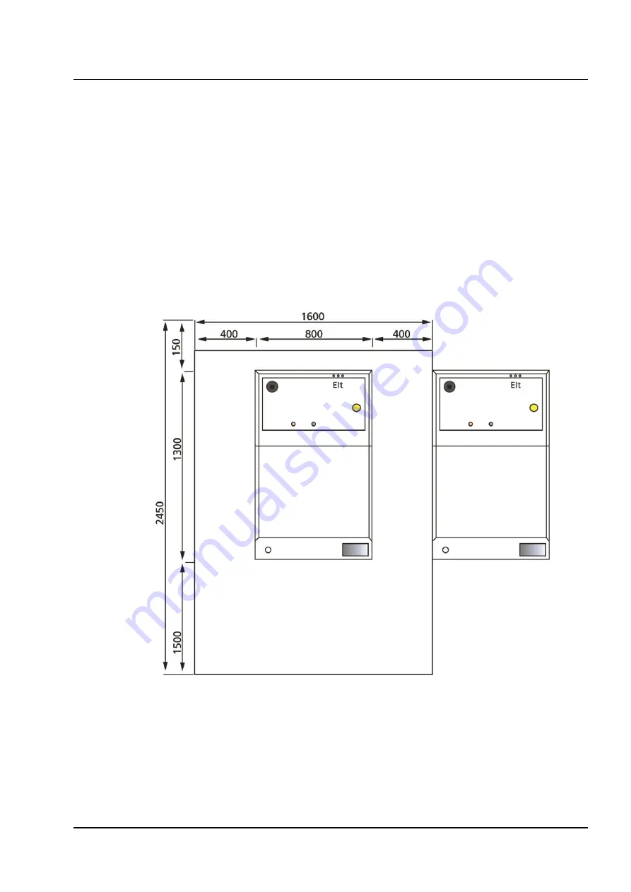
An open area (working area) is required for all work on the CHP plant, in particular 
installation, maintenance and service. For work in front of the CHP plant (front), a larger 
clearance is required in order to be able to remove and insert the equipment set (engine 
and generator). The room height should be at least 2,000 mm. Deviations from the 
specified minimum dimensions may involve additional work and are only possible after 
consultation. 

Please also refer to the 

Figure 6: Installation diagram

 for the defined dimensions for 

determining the total space requirement. The dimensions and weights of the individual 
plant components can be found in the manufacturer's specifications in the technical 
documentation. 


Figure 6: Installation diagram 

The  dimensions  are  given  in  "mm"  and  depend  on  the  external  dimensions  of  the  CHP 
plant. 


Summary of Contents for PowerBloc EG

Page 1: ...Subject to modification Operating and installation manual Hoval PowerBloc EG 12 15 20 Hoval PowerBloc FG 12 15 20 4 218 891 00 09 20...

Page 2: ...3 3 1 DANGER marking 13 3 3 2 WARNING marking 13 3 3 3 CAUTION marking 15 3 3 4 IMPORTANT marking 15 3 4 Waste disposal 16 3 5 Intended use of the plant 16 3 5 1 General 16 3 5 2 Possible misuse 17 3...

Page 3: ...diagram 49 4 4 15 Power supply 51 5 Commissioning and decommissioning 52 5 1 Commissioning 53 5 1 1 Safety 53 5 1 2 Assembly and installation 54 5 1 3 Preparatory work for installation of the CHP pla...

Page 4: ...number menu structure 2 6 14 104 6 7 7 Temperature configuration menu structure 2 6 15 105 6 7 8 Manual control menu structure 2 6 16 106 6 7 9 Other parameters menu structure 2 6 17 107 6 8 Stop mod...

Page 5: ...step forward is the innovative control system CHP plants with static control only adapt moderately to the change in demand parameters Thanks to dynamic control modules the CHP plant adapts to differe...

Page 6: ...validate the warranty as shall any modification or repair to the plant without the prior written consent of Hoval Furthermore Hoval shall not be liable for damage or accidents caused by improper handl...

Page 7: ...purpose the plant is only operated in perfect functional condition and the safety devices in particular are regularly checked for their functionality the necessary personal protective equipment is ava...

Page 8: ...ontrol Ordinance MFeuVo Model firing ordinance of the federal states FeuVo Fundamental standards DIN EN ISO 60204 1 Safety of machinery Electrical equipment of machines DIN EN ISO 12100 Safety of mach...

Page 9: ...or interactive systems DIN EN ISO 6826 Reciprocating internal combustion engines fire protection DIN ISO 8528 ff Reciprocating internal combustion engine driven alternating current generating sets DIN...

Page 10: ...that are already acute at the moment of the warning Warning of dangerous situations which if not avoided will result in serious injury or death WARNING Warning of personal injuries that depend on beh...

Page 11: ...htrenk 43 50 365 0 info hoval at Germany Hoval GmbH Humboldtstrasse 30 85609 Aschheim Dornach 49 89 922 097 0 info de hoval com Italy Hoval s r l Via XXV Aprile 1945 snc 24050 Zanica BG 39 035 6661111...

Page 12: ...s only allowed to be operated by persons who have been instructed and informed about the dangers It is recommended that service personnel be consulted for instruction 3 1 2 Qualification of the person...

Page 13: ...WARNING Warning of slipping hazard Care must be taken when walking running or climbing because of the danger of slipping on traffic routes in exceptional situations e g after cleaning work or in the e...

Page 14: ...er of electric shocks Electrical hazards to persons due to direct contact with live parts Elements likely to present an electrical hazard must be positioned or protected in such a way that they cannot...

Page 15: ...tion Use foot protection Safety shoes must be worn to protect the feet from foot injuries Foot injuries can be caused by tools or workpieces falling over or down incorrectly attached loads jamming of...

Page 16: ...ion signs must not be removed and must always be in a legible condition Protective devices must not be modified or dismantled They must be checked regularly for function The CHP plant is a compact rea...

Page 17: ...the work area Only use suitable extinguishing agents for extinguishing fires There is a risk of fire and explosion when cleaning with cleaning agents which can lead to fire and explosion 3 5 4 Mechan...

Page 18: ...alist personnel Installation commissioning maintenance and repairs to the CHP plant are only allowed to be carried out by qualified installers Maintenance The CHP plant must be serviced and inspected...

Page 19: ...nation during the building phase If the CHP plant is installed during the building phase the electronics and the air filter must be checked and cleaned after completion of the construction Installatio...

Page 20: ...for damage caused by the non observance of these operating instructions Corrosion protection Do not use sprays solvents chlorine based cleansing agents paints adhesives etc in the proximity of the un...

Page 21: ...P plant can be operated both thermally heat guided and electrically current optimised 3 7 2 Generator protection When asynchronous motors are operated parallel to the mains the mains parameters are th...

Page 22: ...The base frame is equipped with corresponding openings for transport with a forklift or lift truck The engine generator unit is flexibly mounted on the base frame by means of rubber metal pads which h...

Page 23: ...l change takes place every 2000 operating hours A second external electric pump is responsible for extracting the used oil from the engine This used oil is then pumped into a used oil canister in the...

Page 24: ...to the heating water The exhaust gas heat exchanger is designed as an aluminium casting The plate heat exchanger transmits the heat from the engine coolant circuit to the heating water circuit The pl...

Page 25: ...nder certain circumstances may be charged by the grid operator By using an output capacitor directly on the plant it is possible to reduce the load on the transmission devices because the necessary re...

Page 26: ...as equipment carrier Electronically controlled industrial engine from Volkswagen 4 cylinder 2 0 l Water cooled asynchronous generator in completely encapsulated design with vibration decoupling for ge...

Page 27: ...reby guaranteeing low standstill times with optimum electricity yield and also offering ease of maintenance The combined heat and power plants are assembled ready for operation and are subject to a th...

Page 28: ...packaging The plant is only allowed to be lifted at the holding points provided The specified position for the transport of the plant must be adhered to exactly Only the specified load bearing and sli...

Page 29: ...ciated components which cannot be set up immediately at the place of installation are protected in their packaging against weather and external influences The following storage requirements apply Leav...

Page 30: ...long the ground dismantled or also by means of a load crane Please contact Hoval regarding disassembly for transport to the installation location When using a load crane the CHP plant must be lifted a...

Page 31: ...Assembly and installation 1 Remove the packaging cardboard box and foil bag 2 Assembly of the heating circuit pump Please screw the heating circuit pump 1 onto the connection according to the picture...

Page 32: ...of 131 3 Please mount the Wilo heating circuit pump at a 45 angle cables are permanently connected 4 Assembly of the heating circuit return connection Please screw the heating circuit return onto the...

Page 33: ...t to any loading do not damage it 5 Assembly of the pre silencer For this purpose please remove the left casing covering and mount the pre silencer 1 on the lower connection 2 for easier mounting of t...

Page 34: ...fications 34 of 131 6 Assembly of the condensate trap For this purpose please mount the condensate trap 1 on the pre silencer 2 for easier mounting of the condensate trap apply lubricant for plug in s...

Page 35: ...Technical documentation Subject to modifications 35 of 131 Please align the condensate trap so that the siphon points to the rear and secure it with 4 countersunk screws M5 x 16 mm...

Page 36: ...C62 installation room air independent For this purpose please push the corrugated suction hose 1 onto the connection at the condensate trap 2 and secure it with the hose clamp 3 8 Assembly for B23 in...

Page 37: ...tion conditions The installation conditions shown here must be complied with Installation is only allowed to be performed by specialist personnel 1 Prior to commissioning the CHP plant must be placed...

Page 38: ...ll open and accessible sharp edged plant components Live cable ends and components can lead to injuries from electric power Loose parts lying on top of each other can slip and fall down Lines that are...

Page 39: ...t remove guards and covers Check protective devices for completeness and proper fastening before each time the plant is switched on After completion of installation or maintenance work all protective...

Page 40: ...rine Air temperature as constant as possible within the range 10 C 35 C with low temperature fluctuations CAUTION Engine damage Ammonia and chlorine in the intake air can damage the engine and shorten...

Page 41: ...e and nitrous oxides When the water vapour condenses in downstream components these nitrous oxides are converted into dilute nitric acid and sulphuric acid The largest quantities of condensate are for...

Page 42: ...t the CHP plant s continuous output 20 kW CHP plant or 40 kW for a double module plant can be transmitted on a continuous basis The building s own SLS switch must have the C characteristic The CHP pla...

Page 43: ...de plant into the heating circuit of the building takes place as in the sample application of the individual plant via the coupling to the buffer storage tank The CHP plant modules are connected in pa...

Page 44: ...omplied with Non observance will void the warranty The CHP plant is connected to the supply and return lines via sufficiently sized pipes in which case a common larger pipe can be used for multi modul...

Page 45: ...ensured that a heating water flow of at least 1 8 m h always flows through the CHP plant This prevents overheating and possible damage to the plant For filling the CHP plants an outlet tap with connec...

Page 46: ...10 Floor and base The CHP plant is a stationary plant The floor condition must be aligned and determined according to the weight of the installation The base must be level and dust free 4 4 11 Water q...

Page 47: ...ront a larger clearance is required in order to be able to remove and insert the equipment set engine and generator The room height should be at least 2 000 mm Deviations from the specified minimum di...

Page 48: ...lity VDI 2035 Fuel system Gas connection DN 20 3 4 external thread conically sealing Flow pressure 2 0 to 6 0 kPa 20 to 60 mbar on the unit Methane number Minimum 65 Exhaust system Exhaust gas connect...

Page 49: ...n installing the connections the installation plan for the CHP plant must also be taken into account especially with regard to the minimum free surfaces to be observed RT Heating return Connection DN...

Page 50: ...chnical documentation Subject to modifications 50 of 131 Figure 7 Connection diagram 1 Figure 8 Connection diagram 2 The dimensions are given in mm and depend on the external dimensions of the CHP pla...

Page 51: ...Technical documentation Subject to modifications 51 of 131 4 4 15 Power supply Circuit diagram for full supply Figure 9 Circuit diagram for full supply...

Page 52: ...um volume flow of 1 8 m h must flow through the CHP plant The hydraulic system of the heating circuit must be provided on site A sludge filter is highly recommended Otherwise there is a risk of damage...

Page 53: ...out by qualified persons in compliance with the safety instructions Ensure that a permissible floor load is guaranteed at the installation site of the CHP plant The total weight of the CHP plant must...

Page 54: ...plied within the specified tolerances and specifications If there are deviations immediately inform the people responsible 5 1 4 Installing the CHP plant Make sure that all preparatory steps have been...

Page 55: ...oning Initial commissioning is only allowed to be performed by specialist personnel An employee of Hoval or a service partner must be present at the time of initial commissioning The CHP plant and all...

Page 56: ...ipment is allowed to be used to lift the CHP plant When selecting suitable load bearing equipment the total weight of the CHP plant must always be taken into account Observe the permissible floor load...

Page 57: ...disposal If scrapping is planned the various materials used must be taken into account The CHP plant consists of various metals such as steel and aluminium as well as copper wire as part of the elect...

Page 58: ...ntion to the notes marked as follows 6 2 Menu structure The controller has a 7 touch panel that enables you to navigate through the menu structure intuitively You can quickly obtain the required infor...

Page 59: ...curve 2 2 Schedule 2 3 Time Date 2 4 LAN 2 5 E mail 2 6 Additional functions 2 6 1 Binary outputs 2 6 2 Boiler block 2 6 3 Cascade 2 6 4 Thermal load connection 2 6 5 Speed controlled pump control 2...

Page 60: ...rther information The main screen shows 10 areas Figure 10 ATROMATIC main screen 1 At the top left is the current date and time 2 In this area you can see the individual serial number of the CHP plant...

Page 61: ...off and a soft shutdown is performed The Hard stop appears below the Off button Pressing the Hard stop button switches off the CHP plant quickly hard stop not recommended 7 Details After pressing this...

Page 62: ...is automatically stopped after 10 minutes If the measurements have been completed before the function can also be stopped manually Within this window helpful data is available to the chimney sweep po...

Page 63: ...d the following window opens Figure 12 Menu Details 6 4 1 History Menu structure 1 1 When you press the History button you reach the menu structure 1 1 and the following window opens The history inclu...

Page 64: ...bH 64 of 131 Year data menu structure 1 1 1 When you press the Year data button the following window opens Use the arrow keys see point 1 of the figure to go to the desired year for which you want to...

Page 65: ...al power Menu structure 1 1 2 When you press the Electrical power button the following window appears in which you can call up the display of the electrical power produced on a daily weekly or monthly...

Page 66: ...Subject to modifications A TRON Blockheizkraftwerke GmbH 66 of 131 Figure 17 Menu Electrical power 3 Figure 18 Menu Electrical power 4...

Page 67: ...ast seven days Temperatures Week of generator winding engine oil heating circuit return heating circuit flow outside temperature exhaust gas engine coolant inlet and engine coolant outlet Figure 19 Me...

Page 68: ...Subject to modifications A TRON Blockheizkraftwerke GmbH 68 of 131 Figure 21 Menu Temperatures 3...

Page 69: ...opens This window contains a list of the error history The Details button is located to the right of the respective error message see point 1 of the figure When this button is pressed the details of t...

Page 70: ...nge of parameters emergency stop switch pressed etc are listed saved and displayed All processes listed here are saved and can no longer be changed Figure 24 Menu Log history Warning history Menu stru...

Page 71: ...since the time of commissioning 4 Operating hours counter Display of the total operating hours of the CHP plant running operation since the time of commissioning 5 Starts Display of all start process...

Page 72: ...he last 30 minutes are also recorded see figure Figure 27 Menu Temperatures details 1 Recorded temperatures Recorded values from the last 30 minutes 2 Current temperatures Click on the respective butt...

Page 73: ...used oil out of the engine and pumping it into the used oil tank Then fresh oil is pumped out of the fresh oil tank into the engine The CHP plant starts automatically after the automatic oil change ha...

Page 74: ...information about the currently set Maximum effective electrical power as well as the status of the NA protection the Internal network monitoring the External release digital and the External hard st...

Page 75: ...tains setting options that the customer operator can carry out independently following instruction from the service technician User level 2 contains additional setting options for service technicians...

Page 76: ...tures of the heating circuit return flow If the temperature of the heating circuit return falls below the restart temperature the CHP plant restarts 3 Switch off temperature If the temperature of the...

Page 77: ...set the CHP plant automatically to standby mode see point 1 of the figure After making the appropriate selection you can create the respective Daily or Weekly schedule see point 2 of the figure Figur...

Page 78: ...time window is activated here in the example Weekly Monday Time window 1 is selected see point 1 of the figure the CHP plant can be switched off see point 3 of the figure or a maximum power can be spe...

Page 79: ...ote that the time windows can only be set between 0 h and 24 h Time settings beyond the daily schedule 00 00 h are not taken into account 6 6 3 Time date menu structure 2 3 After pressing the Time Dat...

Page 80: ...rmation was already available to Hoval the following boxes will have been filled in already If any changes are required tap the desired box see point 1 and enter the new IP address The same applies to...

Page 81: ...outer allows fixed IP addresses and does not assign them by DHCP If necessary contact your IT employee or the Hoval service technician In order to be able to restart the control unit after changes poi...

Page 82: ...espective e mail addresses must be separated with a semicolon Further e mail recipients of status messages can also be entered in the line below Email CC recipient For notifications of power messages...

Page 83: ...an be purchased as optional additional packages Figure 39 Menu Additional functions The standard equipment includes the following functions 1 Boiler block 2 Binary outputs 3 Cascade 4 Thermal load con...

Page 84: ...ial free contacts are switched which can be freely selected in the menu Simply click the desired message e g Collective fault messages on binary output 1 point 1 All error messages are then transmitte...

Page 85: ...on checks the heating circuit return temperature around the modulation start point of the power curve As soon as the temperature rises above the set value for Boiler block ON for the boiler block is s...

Page 86: ...HP plant control unit is connected to the router or switch via a LAN cable so that communication between CHP plants can be guaranteed The respective CHP plants must also be marked either as Master or...

Page 87: ...5 After successful initialisation and the specifying the characteristic curves the cascade can be started and the master CHP plant starts transferring the power curves to the respective slave CHP pla...

Page 88: ...see point 3 The sequence indicates the identification number on the slave CHP plant The IP number entered on the master CHP plant must match the IP number entered on the respective slave CHP plant Onc...

Page 89: ...Differences of 5 degrees Celsius within the cascade should be taken into account The individual values can be changed by tapping the respective box The assignment of the cascade position numbers and...

Page 90: ...cascade depends on the number of operating hours of the CHP plant and can be changed Possibility of setting the identification as master CHP plant or slave CHP plant When setting as slave CHP plant t...

Page 91: ...unction allows emergency cooling of the Hoval Eco Plus CHP plant to be controlled in biogas and or sewage gas operation This function can also be optionally used for control of another heating circuit...

Page 92: ...ent 4 7 I component 90 100 D component Always set to 0 otherwise the pump could be controlled defectively Limit values minimum 8 maximum 100 The P I components are to be adjusted on site within this f...

Page 93: ...included in the scope of delivery To activate the storage tank filling level control press the Yes button Then select the number of installed sensors on the left hand side 6 6 6 7 Storage tank chargin...

Page 94: ...op switching contact is exceeded the discharge pump is switched on If the value falls below the T bottom switching contact the discharge pump is switched off 6 13 6 6 9 Boiler block 6 13 6 6 9 1 The b...

Page 95: ...is released Notice All switching contacts can be provided with a time delay It is recommended to select the temperature values in such a way that the CHP plant always takes priority over other heat ge...

Page 96: ...to CHP plant See enclosed circuit diagram page 19 Notice Work on the CHP plant and the connection of electronic components is only allowed to be carried out by qualified personnel 6 6 8 M BUS menu str...

Page 97: ...Blockheizkraftwerke GmbH 97 of 131 For connection to CHP plant See enclosed circuit diagram page 19 Notice Work on the CHP plant and the connection of electronic components is only allowed to be carr...

Page 98: ...ckheizkraftwerke GmbH 98 of 131 6 7 User level 2 After you have entered your password for user level 2 the name Code changes to Setup When you press the Setup button again the following extended menu...

Page 99: ...izkraftwerke GmbH 99 of 131 6 7 1 Oil change menu structure 2 6 9 Figure 49 Menu Oil change 1 In this area settings for the automatic oil change can be made 2 Confirming by pressing the Next page butt...

Page 100: ...e interval menu structure 2 6 10 Every regular maintenance is recorded via the Service interval menu item An oil change must be carried out with every maintenance which is also confirmed Figure 50 Men...

Page 101: ...for a current controlled operation mode of the CHP plant by e g an energy supplier or network operator 3 Shows the settings of an input signal e g from a balance point control unit for a current optim...

Page 102: ...pped and an error message is output error oil level check error code 27 Figure 52 Menu Fresh oil pump 1 The test cycle for the engine oil level can be set with this parameter 2 If the oil level is too...

Page 103: ...6 7 5 System operator menu structure 2 6 13 This menu item is used to enter the plant owner This setting is carried out at the factory and is only allowed to be changed by Hoval or by qualified perso...

Page 104: ...ON Blockheizkraftwerke GmbH 104 of 131 6 7 6 Serial number menu structure 2 6 14 This menu item is used to enter the serial number This setting is made at the factory and is not allowed to be changed...

Page 105: ...raftwerke GmbH 105 of 131 6 7 7 Temperature configuration menu structure 2 6 15 Allows you to calibrate individual temperature probes and create warning and shutdown limits as well as the response tim...

Page 106: ...enu structure 2 6 16 Sets the CHP plant into manual control mode and thus enables testing of the individual components This function is only allowed to be used by Hoval or by qualified personnel appro...

Page 107: ...tructure 2 6 17 This menu item can be used to make changes to various setting parameters for automatic and control mode as well as for the basic settings These functions are only allowed to be used by...

Page 108: ...by Hoval or by qualified personnel approved and certified by Hoval Points 1 4 are used for heating optimisation All other parameters are factory set and must not be changed Figure 59 Menu Automatic m...

Page 109: ...6 7 9 2 Control menu structure 2 6 17 2 The parameters for the control mode are set at the factory and are not allowed to be changed with the exception of Lambda value minimum and Lambda value maximu...

Page 110: ...operating hours until the next service interval 3 Shows the number of operating hours 4 Shows the number of starts 5 Shows the number of oil changes that have already taken place 6 This box can be use...

Page 111: ...anges are only allowed to be carried out by Hoval or by qualified personnel approved and certified by Hoval Figure 62 Menu Miscellaneous 6 7 10 Save load parameters menu structure 2 6 18 In this menu...

Page 112: ...tory employee so that the CHP plant can be adapted to local conditions In the event of an error the operation of the CHP plant is stopped in a rapid process in order to avoid damage It can only be res...

Page 113: ...twerke GmbH 113 of 131 Figure 64 Menu Error example You can get more information about the errors by clicking the Info button To return the CHP plant to the error free status the error can be reset wi...

Page 114: ...hnician Hoval in the event of an error and state the error and the associated error code Follow the instructions on the screen to correct the error In this example Network check point 3 an error has o...

Page 115: ...ed of rotation not reached Start phase The speed of rotation was not reached within the specified time No gas spark plugs engine control unit 9 Start procedure Gas pressure not reached The gas pressur...

Page 116: ...ow temperature Heating circuit flow temperature is high Heating pump air in system sensor 26 Power system connection protective device NA BISI Waiting for power system enable by power system plant pro...

Page 117: ...ant Check power system voltage check fuses 43 Error power system voltage L3 N Error Voltage L3 N Check the electrical connection to your CHP plant Check power system voltage check fuses 44 Frequency e...

Page 118: ...status with a yellow warning triangle Warning window If you click the warning triangle symbol in the main screen a window appears with the existing errors point 1 There are two current warning pages w...

Page 119: ...the warnings by clicking the Info button In the case of increased temperatures such as here in the example the exhaust gas temperature point 3 the CHP plant output is reduced until the normal conditio...

Page 120: ...GmbH 120 of 131 6 10 Standards The control unit complies with the following standards DIN EN ISO 12100 DIN EN 954 1 Safety of machinery DIN EN 60204 Electrical equipment of industrial machinery EN 50...

Page 121: ...correctly e g with insufficient bending radius can cause smouldering or cable fires Leaking lubricants solvents preservatives cleansing agents etc can cause burns if they come into direct contact with...

Page 122: ...specialist personnel must be called in Cleaning and lubrication work are only allowed to be carried out by authorised specialist personnel The maintenance instructions and accident prevention regulat...

Page 123: ...ate lifting gear and load handling equipment are available for replacing larger plant components Cordon off access to the working area of the CHP plant and make sure that no unauthorised persons are i...

Page 124: ...rating instructions as well as the functional description and the electrical diagrams A detailed description of the controller is included in the separate documentation 7 6 Connecting to the electrica...

Page 125: ...ains voltage at the main switch 1 Remove the cover from the top of the control panel and mount the remote maintenance module on the top hat rail inside the control panel as shown in the photograph You...

Page 126: ...iLink USB 2 0 network adapter supplied with the remote maintenance module into one of the USB ports on the module Plug a network cable into the other side of the adapter and connect this to your home...

Page 127: ...the code 2010 and press the OK button to confirm Next press the LAN button The following character string should appear in the yellow IP address box at the top 10 0 20 1 If this character string is n...

Page 128: ...e network requires a static IP this must be set by Hoval prior to delivery of the remote maintenance module 8 3 Cascade connection If multiple CHP plants are connected in a cascade only the master CHP...

Page 129: ...disconnecting the CHP unit from the supply voltage Then carefully remove the remote maintenance module from the top hat rail Next carefully pull out the old Micro SD card and insert the new one The si...

Page 130: ...Subject to modifications A TRON Blockheizkraftwerke 130 of 131 8 5 Connection diagram for the remote maintenance module 8 5 1 Connecting the individual CHP plant...

Page 131: ...Subject to modifications A TRON Blockheizkraftwerke 131 of 131 8 5 2 Connecting the CHP plant cascade...

Reviews: