background image

Page 11 of 18 

Setting Configuration Variables in the Radar: 


1.  Install the provide Houston Radar Advanced Stats Analyzer Windows program on 

a Windows 2000, XP or Vista computer. 

2.  Connect the radar RS232 port to the PC’s RS232 serial port. If the PC does not 

have a serial port you may buy a USB serial converter dongle (from BestBuy, 
Radioshack or any Internet store). 

3.  Power up the radar.  
4.  Start the Houston Radar Stats Analyzer program on the computer (Start->All 

Programs->Houston Radar->Houston Radar Stats Analyzer) 

5.  In the program window, click on Start->Connect to Radar… 
6.  Click on “Connect” button. 
7.  Ensure you see a “Radar found on COM” message. The COM # will depend on 

your computer . 

8.  Click on OK. Now you are ready to configure the radar. 
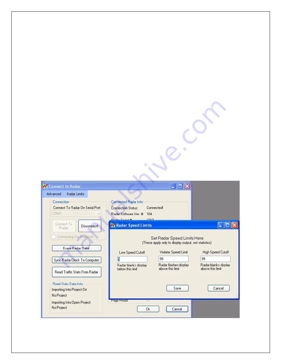
9.  To configure the LO, SP & HI limits, click on “Radar Limits” menu bar item. The 

three fields show the current values of the three variables. Change the variables to 
the desired values and click on “Save”. 

10. To configure any other variable, click on “Advanced->Radar Configuration”. In 

the window that comes up, enter the two letter variable name in the “Variable” 
field (from the table on previous page). Enter its value in the “Value” field and 
click on “Set Variable” button. 


Summary of Contents for DR500

Page 1: ... 18 Houston Radar LLC Installation and User Manual For K Band Doppler Radar DR500 Houston Radar LLC 13814 Sherburn Manor Dr Cypress TX Http www Houston Radar com Email sales Houston Radar com Rev 9 May 19th 2009 ...

Page 2: ...d including interference that may cause undesired operation This device conforms to the CE mark and conforms to the requirements of the applicable European Directives as follows EN 60950 1 ETSI EN 300 440 1 V1 4 1 ETSI EN 300 440 2 V1 2 1 ETSI EN 301 489 1 V1 7 1 EN 55022 Class B EN 61000 4 2 8 kV 4 kV EN 61000 4 3 3 V m Note Specifications may change without notice Note Not liable for typographic...

Page 3: ...IN RADAR TRAFFIC STATISTICS 9 CONFIGURING THE RADAR 10 SETTING CONFIGURATION VARIABLES IN THE RADAR 11 OPTIONAL INFRARED REMOTE PROGRAMMING 12 Speed Low Limit 13 Speed High Limit 13 Speed Limit 13 Detection Sensitivity 14 Internal Clock 14 Self Test 15 Display Units MPH or KMPH 15 Reset Factor Settings 15 Set Serial Baud Rate 16 DR500 SPECIFICATIONS 17 GENERAL 17 APPROVALS 17 DATA INTERFACES 17 ME...

Page 4: ...ed trailers o Use in school zones 2nd True serial port option available Now connect to different devices simultaneously Only 0 7 W power usage is up to 4X lower vs competing solutions and allows use of smaller batteries and solar panels saving you money Rugged weatherproof enclosure features side mounts and short depth DR500S only Built in clock calendar keeps time even with DC power removed Only ...

Page 5: ...median without worry of picking up traffic on the outgoing lane For optimal performance Radar should be mounted with the mounting bosses horizontal to the road Radar should be pointed into the direction of the oncoming traffic Radar should be placed along the size of the road to minimize the angle of the oncoming traffic to the radar o If radar cannot be placed right along the side of the road it ...

Page 6: ...les are detected the radar outputs 000 r n or 000 r n once or repeating depending on configuration This format is compatible with other industry formats including a standard RS232 serial port on a PC message boards and speed displays Note Optionally the radar may be set to output the display speed in nnn r format Please see serial port config settings table later section Setting Detection Sensitiv...

Page 7: ...at different speeds simultaneously and hence does not miss vehicles visible to it Radar access to all return signal parameters of the target vehicles processed by proprietary software inside radar makes full use of every bit of information present in reflected signal and dramatically improves counting accuracy No add on boards keeps total system power usage down and reliability up Advanced Statist...

Page 8: ...current flows into this terminal when it is pulled low Note The case of the radar is connected to GND i e pin 5 and 9 DB9 Pin Signal Name Direction wrt Radar Description 1 12V DC Input Radar Power Supply Connect to battery 9 5VDC to 18VDC 2 RS 232 TX Output Primary RS232 transmit output from Radar 3 RS 232 RX Input Primary RS232 receive input Required only if connected to PC to download stats from...

Page 9: ...s up from 000 to 010 to provide a quite visual check that it is operational If you use the RED Stdby button on the IR remote control to put the radar in standby mode it counts down from 010 to 000 to provide a quick visual check that it powered down Collecting and Analyzing In Radar Traffic Statistics The DR500 Radar supports optional In Radar advanced traffic statistics collection This feature is...

Page 10: ...r than LO speed SP Flashing speed limit Any speed higher than this value flashes the trigger output at 2 3 duty cycle 1Hz ST Target detection sensitivity Valid values are from 10 to 99 and are a percentage of max range So a value of 50 would yield about 750 feet detection Note This is not range setting but detection sensitivity Thus if large vehicles are being detected at 2000 feet a value of 50 w...

Page 11: ...dar Stats Analyzer 5 In the program window click on Start Connect to Radar 6 Click on Connect button 7 Ensure you see a Radar found on COM message The COM will depend on your computer 8 Click on OK Now you are ready to configure the radar 9 To configure the LO SP HI limits click on Radar Limits menu bar item The three fields show the current values of the three variables Change the variables to th...

Page 12: ... be programmed in conjunction with speed display panels that support visual feedback of ASCII chars sent on the serial data line Contact the factory for availability and a list of panels that support this feature However the Houston Radar LED panels do support this feature THE IR REMOTE CONTROL IS NOT REQUIRED FOR BASIC SPEED DETECTION AND OPERATION OF THE RADAR Optional DR500S Remote Control ...

Page 13: ... current value will be displayed on the display 2 Enter the numeric speed for the low limit or use the Up Down arrow keys 3 Press SET OK to save the limit in the radar or press CANCEL at any time before SET OK to cancel this operation Speed High Limit Use this feature to blank out the speed display of vehicles over this limit You can use this feature to defeat racing against the radar issue 1 Pres...

Page 14: ...you have purchased the optional statistics collection package The unit will keep time even with external power removed It may be more convenient to set the clock of the radar by connecting a serial cable to the radar and using the Houston Radar Stats Analyzer program A button in the program allows you to sync the radar clock with your computer clock However the following steps may be used in the f...

Page 15: ...ram you may conduct a more detailed self test Contact Houston Radar for details Display Units MPH or KMPH 1 Press the F1 key on the remote The radar will display F1 2 Press the 4 key The radar will display the current value code 0 MPH 1 KPH 3 Press 0 to display speed in MPH or 1 to display speed in KPH 4 Press SET OK key to save in memory Radar will restart and count up from 1 to 9 and the display...

Page 16: ...s not stored and changed till you press the Set OK key Your baud rate is now programmed in permanent memory and if you have speed display panels hooked up they will display the two digit key combination that you entered to select the baud rate If you want to change the baud rate of the radar you can simply follow the above procedure and select a new baud rate any number of times Baud Rate bps Data...

Page 17: ...Part 15 CE European R TTE directive 1999 5 EC EN 60950 1 ETSI EN 300 440 1 V1 4 1 ETSI EN 300 440 2 V1 2 1 ETSI EN 301 489 1 V1 7 1 EN 55022 Class B EN 61000 4 2 8 kV 4 kV EN 61000 4 3 3 V m Data Interfaces Serial Communication RS232 RS485 optional 2nd True serial port option Data Rate Baud Rates from 1200 to 115200 baud Data Format Selectable via IR Remote or serial port or factory set Please ref...

Page 18: ... road conditions Advanced Statistics Storage Last 60 days in 5 min bins 20 5 mph speed bins mph mode Last 60 days in 5 minute bins 17 10 kph bins in kph mode Multi vehicle capable Yes in multiple lanes for approaching traffic Internal Clock Battery Life At least 3 years on the shelf with radar un powered 7 years under normal radar operation in the field Note Advanced Statistics is sold as an optio...

Reviews: