background image

27536-0-0610

Page 12

installing a new Main Gas cock

Each appliance should have its own manual gas cock.
A  manual  main  gas  cock  should  be  located  in  the  vicinity  of 

the unit. Where none exists, or where its size or location is not 

adequate, contact your local authorized installer for installation 

or relocation.
Compounds used on threaded joints of gas piping shall be resistant 

to the action of liquefied petroleum gases. The gas lines must be 

checked for leaks by the installer. This should be done with a soap 

solution watching for bubbles on all exposed connections, and if 

unexposed, a pressure test should be made. 

Never use an exposed flame to check for leaks. Appliance must be 

disconnected from piping at inlet of control valve  and pipe capped 

or plugged for pressure test. Never pressure test with appliance 

connected; control valve will sustain damage!

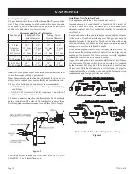
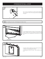
A gas valve and ground joint union should be installed in the gas 

line upstream of the gas control to aid in servicing. It is required 

by the National Fuel Gas Code that a drip line be installed near 

the gas inlet. This should consist of a vertical length of pipe tee 

connected into the gas line that is capped on the bottom in which 

condensation and foreign particles may collect. 

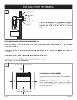
Method of installing a tee Fitting Sediment trap

Figure 2

locating Gas Supply

The gas line can enter the unit either through the floor or outside 

wall.  The gas line opening should be made at this time.  Location 

of the opening will be determined by the position of floor joists 

and the valve and union used for servicing.

note:

 Never use plastic pipe. Check to confirm whether your local 

codes allow copper tubing or galvanized.

note: 

Since some municipalities have additional local codes, it is 

always best to consult your local authority and installation code.
The use of the following gas connectors is recommended:

—  ANS Z21.24 Appliance Connectors of Corrugated Metal Tubing 

and Fittings

—  ANS Z21.45 Assembled Flexible Appliance Connectors of 

Other Than All-Metal Construction

The above connectors may be used if acceptable by the authority 

having  jurisdiction.  The  state  of  Massachusetts  requires  that  a 

flexible appliance connector cannot exceed three feet in length.
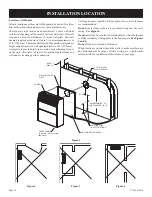
Figure 1 

Consult the current National Fuel Gas Code, ANSI Z223.1 CAN/

CGA-B149 (.1 or .2) installation code. 
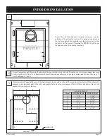
GaS SuPPlY

recommended Gas Pipe Diameter

Pipe Length

Schedule 40 Pipe

Inside Diameter

Tubing, Type L 

Outside Diameter

Nat.

L.P.

Nat.

L.P.

0-10 feet

0-3 meters

1/2”

12.7 mm

3/8”

9.5 mm

1/2”

12.7 mm

3/8”

9.5 mm

10-40 feet

4-12 meters

1/2”

12.7 mm

1/2”

12.7 mm

5/8”

15.9 mm

1/2”

12.7 mm

40-100 feet

13-30 meters

1/2”

12.7 mm

1/2”

12.7 mm

3/4”

19 mm

1/2”

12.7 mm

100-150 feet

31-46 meters

3/4”

19 mm

1/2”

12.7 mm

7/8”

22.2 mm

3/4”

19 mm

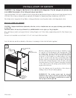
FLEXIBLE GAS LINE CONNECTION

RIGID GAS LINE CONNECTION

GAS SUPPLY

TEE HANDLE

FLEX TUBE

NPT NIPPLE

REGULATOR

VALVE

FLARE FITTING

FLARE SHUT OFF VALVE

CLOSE NIPPLE

TEE HANDLE

3/8 NIPPLE

REGULATOR

VALVE

NPT GAS SUPPLY

SHUT OFF VALVE

NPT UNION

Summary of Contents for HWDV080BDVN-2

Page 1: ...nual with the ap pliance Consumer Retain this manual for future reference Do not store or use gasoline or other flam mable vapors and liquids in the vicinity of this or any other appliance WHAT TO DO...

Page 2: ...Location 14 Installation Overview 15 16 Interior Installation 17 20 Cutting the Vent Tubes 21 22 Exterior Installation of the Venting 23 25 Reassembly and Resealing Vent Air Intake System 26 28 Insta...

Page 3: ...IRECT VENT HEATER INSIDE WALL MOUNTING PLATE ATTACHED ON BACK INLET OUTLET TUBES INSTALLATION TEMPLATE TEMPLATE FOR HWDV080 ON REVERSE SIDE OUTSIDE WALL MOUNTING PLATE VENT CAP VENT KIT HARDWARE PACKE...

Page 4: ...LE WRENCH CAULKING PHILLIPS SCREW DRIVER TAPE MEASURE DRILL SAW FURNACE CEMENT HARDWARE PACKETS PLASTIC TOGGLE 6 10 X 1 SLOTTED HEX HEAD SCREW 6 NYLON WASHER 2 10 X PHILLIPS HEX HEAD SCREW 3 10 X 2 HE...

Page 5: ...16 25 3 16 WIDTH 18 5 16 22 5 16 DEPTH 8 7 8 9 3 8 NET WEIGHT LBS 33 5 45 5 MAX GAS CONSUMPTION 8 000 Btu hr 18 000 Btu hr SAFETY DEVICES Safety valve thermocouple NOTE This direct vent wall furnace...

Page 6: ...27536 0 0610 Page 6 UNIT DIMENSIONS MAKE SURE THAT APPLIANCE IS SUITABLE FOR THE GAS SUPPLY AVAILABLE NATURAL GAS OR PROPANE LP...

Page 7: ...person Heater should be inspected be fore use and at least annually by a qualified service person More frequent cleaning may be required due to ex cessive lint from carpeting bedding material etc It i...

Page 8: ...trailer or area Finally let the service man and firefighters check for escaped gas Have them air out the area before you return Properly trained LP Gas service people should repair the leak then chec...

Page 9: ...G The nearest point of the vent cap should be a minimum horizontal distance of six 6 feet 1 8 m from any pressure regulator In case of regulator malfunction the six 6 feet 1 8 m distance will reduce t...

Page 10: ...r as required in accordance with the aboveprovisionsshallcomplywithNFPA720andbeANSI UL 2034 listed and IAS certified 3 SIGNAGE Ametal or plastic identification plate shall be per manently mounted to t...

Page 11: ...supply inlet to building or the combustion air inlet to any other appliance 6 inches 152 mm for appliance 10 000 Btuh 3 kW 9 inches 229 mm for appliances 10 000 Btuh 3 kW and 50 000 Btuh 15 kW 12 inc...

Page 12: ...outside wall The gas line opening should be made at this time Location of the opening will be determined by the position of floor joists and the valve and union used for servicing Note Never use plast...

Page 13: ...The minimum distance from the center of the vent cap to the nearest outside corner or obstruction is 24 610 mm 5 The minimum wall depth is 4 1 2 114 3 mm and the maximum is 12 304 8 mm The use of tube...

Page 14: ...e on the wall Also refer to Figure 3 for positioning the furnace on wall and for locating gas line connection WALL MOUNTING PLATE MIN 4 MAX 12 CASING FRONT PANEL To remove pull out at top and lift up...

Page 15: ...ting system must be properly installed to insure proper and safe operation The venting system must also be properly re installed and re sealed to insure proper and safe operation INSTALLATION OVERVIEW...

Page 16: ...Read the installation instructions thoroughly before cutting or drilling any holes for installation Warning Do not remove any rating plates attached to the unit CLEARANCES TO COMBUSTIBLES Allow clear...

Page 17: ...hole onto the wall Mark the six 6 wall mounting plate screw holes onto the wall The size of the gas inlet hole will depend upon the size of gas pipe coming into the unit See page 17 box 3 and page 18...

Page 18: ...LOOR LINE MARKING FOR GAS INLET HOLE Remove the template from the wall after the holes are marked The hole location markings should be present on the wall 5 Drill a pilot hole inside of the traced cir...

Page 19: ...4 wood screws to attach the wall mounting plate to the wall If installing onto drywall not into a stud anchors must be used 8 Push on bottom of casing door to open it Pivot and remove cas ing door Rem...

Page 20: ...e installation template indications Following your city local and state codes attach the gas line to the unit CAUTION Grasp wrench on regulator when installing gas in let NOTE The gas line can come th...

Page 21: ...LET TUBE AIR INLET TUBE MOUNTING PLATE SCREWS 3X LONG SCREWS 4X CAP NOTE Flue outlet tube and air inlet tube should be measured and cut to the proper length from the back of the unit to the outside wa...

Page 22: ...outlet tube is placed as far as possible onto the collar of flue outlet Mark the 3 76 mm diameter flue outlet tube 2 7 8 73 0 mm beyond the mounting surface for the outside wall plate Remove 3 76 mm d...

Page 23: ...he proper length from the back of the unit to the outside wall of the house There should be little to no venting showing on the outside of the house 4 10 x 2 SCREWS Place caulking not provided beneath...

Page 24: ...ment not provided to 3 76 mm diameter flue outlet collar on combustion chamber and to 3 76 mm diameter collar on vent cap 3 DIA VENT CAP COLLAR FURNACE CEMENT 4 If installing onto vinyl aluminum or an...

Page 25: ...allation of this Housewarmer product is complete Attach vent cap into the 3 76 mm diameter flue outlet tube Attach vent cap to outside wall mounting plate with 3 10 x 1 2 13 mm screws provided EXTERIO...

Page 26: ...ounting plate Apply new caulking beneath the edge of the outside wall mounting plate Use additional caulking to correct uneven wall surface such as clapboard Attach 5 127 mm diameter air inlet tube on...

Page 27: ...REASSEMBLY AND RESEALING VENT AIR INTAKE SYSTEM FLUE OUTLET TUBE COLLAR OF FLUE OUTLET 3 DIA VENT CAP COLLAR FURNACE CEMENT 4 If installing onto a vinyl sided exterior wall attach vinyl siding vent sh...

Page 28: ...resealing vent air intake system is completed Attach vent cap into the 3 76 mm diameter flue outlet tube Attach vent cap to outside wall mounting plate with 3 10 x 1 2 13 mm screws provided REASSEMBL...

Page 29: ...T HW125SCB 1 Removefrontpanelofheaterbyopening thenliftingonesideout then the other Be careful not to loose the white nylon washers on the front panel 2 Disconnect the power cord from the blower assem...

Page 30: ...bilization tabs and attach with four 4 screws provided Note It is necessary to use all four 4 screws to tighten down the blower in order to reduce vibration noise 5 Insert power cord through the hole...

Page 31: ...power cord to blower assembly 7 Attach ground wires from the blower and power cord to the blower mounting bracket 8 Slide fan control into the tabs on the right side of the chamber support INSTALLATIO...

Page 32: ...ify that the plastic washers are still in place on the front panel when replacing it For replacement parts see Parts List on pages 42 and 43 and Parts View on page 44 STRAIN RELIEF INSTALLATION OF OPT...

Page 33: ...during any pressure testing of that system at test pressures in excess of 1 2 psi 3 5 kPa BEFORE OPERATING APPLIANCE DO NOT RECESS INTO WALLS BOOKCASES ETC CHECK THE FOLLOWING BEFORE OPERATING APPLIAN...

Page 34: ...of traffic and away from furniture and draperies 3 4 Do not spray any aerosol near heater when in operation Do not store these elements near appliance Do not place clothing or other flammable material...

Page 35: ...be modified Do not operate this appliance if any parts have been removed for service 7 Do not place flammable elements on or near the heater BEFORE OPERATING APPLIANCE 6 Avoid blocking air inlet and...

Page 36: ...cked for gas tightness by means of leak detector solution soapy water or an equivalent solution as applicable CAUTION Since some leak test solutions including soapy water may cause corrosion or stress...

Page 37: ...ne Follow the gas supplier s instructions If you cannot reach your gas supplier call the fire depart ment C Use only your hands to push in or turn the gas control knob Never use tools If the knob will...

Page 38: ...hnician or gas supplier If the pilot will not stay lit after several tries turn the gas control knob to OFF and call a qualified service techni cian or gas supplier 10 Attention Gas control has an INT...

Page 39: ...e flame Do not mistake it for an improper yellow flame The pilot flame is blue and goes toward the main burner and thermocouple horizontally A slight yellow tip on the flame is normal The pilot flame...

Page 40: ...ualified personnel Cleaning of pilot burner As required Clogging of same To be performed by qualified personnel In case of doubt please check with our Customer Service Department Use soft dry cloth to...

Page 41: ...iping according to installation instructions Difficulties in heating room A Incorrect heater size B Low gas pressure C Partially plugged injector A Contact Service Department for sizing room B Check w...

Page 42: ...HAMBER 8 M155 M155 GASKET OBSERVATION HOLE 9 R1055 R1055 ELECTRODE AND WIRE 10 DV781 DV781 OBSERVATION HOLE COVER 11 R1122 R1122 WING NUT 12 TH275 24644 BURNER 13 R2256 R2256 THERMOCOUPLE 14 R2893 R28...

Page 43: ...LATE OUTSIDE 40 24626 24626 VENT SHIELD 41 TH334 TH334 VENT CAP NOT SHOWN R1081 R1081 PILOT ORIFICE 014 NAT NOT SHOWN R1089 R1089 PILOT ORIFICE 009 LPG NOT SHOWN 24633 24633 HARDWARE PACKAGE HEATER NO...

Page 44: ...27536 0 0610 Page 44 PARTS VIEW 1 2 3 4 5 6 7 8 9 10 11 12 13 14 15 16 17 18 19 20 21 22 23 24 25 26 27 28 29 30 31 32 33 34 35 36 37 38 39 40 41...

Page 45: ...l number serial number type of gas and purchase verification information Your Rights Under State Law This warranty gives you specific legal rights and you may also have other rights which vary from st...

Page 46: ...27536 0 0610 Page 46 SERVICE NOTES...

Page 47: ...27536 0 0610 Page 47 SERVICE NOTES...

Page 48: ...ER is a registered trademark of Empire Comfort Systems Inc www housewarmerproducts com EMPIRE EMPIRE Comfort Systems Manufactured for Empire Comfort Systems Inc 918 Freeburg Ave Belleville IL 62220 PH...

Reviews: