background image

2 of 25

Service Manual UK

Whirlpool UK Appliances Ltd

English

SAFETY NOTES & GENERAL SERVICING ADVICE

1.

This manual is NOT intended as a comprehensive repair/maintenance guide to the appliance.

2.

It should ONLY be used by suitably qualified persons having technical competence applicable 
product knowledge and suitable tools and test equipment.

3.

Servicing of electrical appliances must be undertaken with the appliance disconnected (unplugged) 
from the electrical supply.

4.

Servicing must be preceded by Earth Continuity and Insulation Resistance checks.

5.

Personal safety precautions must be taken to protect against accidents caused by sharp edges on 
metal and plastic parts.

6.

After servicing the appliance must be rechecked for Electrical Safety. In the case of appliances which 
are connected to a water supply (i.e.: Washing Machines, Dishwashers & Food Centres etc.) checks 
must be made for leaks from seals gaskets and pipe work and rectification carried out where 
necessary.

7.

It can be dangerous to attempt ‘DIY repairs / maintenance on complex equipment and the Company 
recommends that any problem with the appliance is referred to its own Service Organisation.

8.

Whilst the Company has endeavoured to ensure the accuracy of the data within this publication they 
cannot hold themselves responsible for any inconvenience or loss occasioned by any error within.

SERIAL NUMBER / INDUSTRIAL CODE EXPLANATION

Serial Number Example

3   10   02   0895

Four remaining digits 

= Build number that day 895th built

Third two digits

 = Day of manufacture 2

nd

 of month

Second two digits

 = Month of manufacture October

First digit

 = Year of manufacture 2013

Industrial Code Example

37   24455   0010

Last four digits = 

0000 original production.

Second five digits

 = COMMERCIAL CODE*

First two digits

 = Factory of origin

* Vital for correct model information and system identification

Other numbers denote major production changes

Summary of Contents for HSFX.1

Page 1: ... Peterborough PE2 9JB Registered in London 106725 Service Information HOTPOINT 60 cm TELESCOPIC COOKER HOOD Model Comm Covered Code HSFX 1 88215 5413450 Issue 1 May 2016 C00383263 SM031321 Changes in this Issue New Service Manual New Model Added ...

Page 2: ...hers Food Centres etc checks must be made for leaks from seals gaskets and pipe work and rectification carried out where necessary 7 It can be dangerous to attempt DIY repairs maintenance on complex equipment and the Company recommends that any problem with the appliance is referred to its own Service Organisation 8 Whilst the Company has endeavoured to ensure the accuracy of the data within this ...

Page 3: ...dustrial Code Explanation 2 Introduction 4 Specifications 4 Disposal 5 Installation 6 12 General Safety 12 13 How to get the Best out of the Cooker Hood 14 Connection 15 Controls 16 Maintenance 17 18 Malfunctions 18 Wiring Diagram 19 Other Items Supplied 20 Dismantling Procedure 21 25 ...

Page 4: ...derneath grease filters Dimensions Height 173 mm Width 598 mm Depth 295 mm 450 mm Weight Unpacked 6 0 kg Packed 7 5 kg Noise Maximum 57 dB Electrical Supply 230 240Volts AC 50Hz Extraction Rate 185 m3 h Total Power 156 Watts Motor 100W Energy Efficiency Class E Lamps 2 x Halogen 28W E14 35 mm Air Outlet 150 mm Carbon Filter Supplied Grease Filter Supplied x 2 Mains Cable 1 5 m HO5VV F 2 x 0 75mm2 ...

Page 5: ... Old Electrical Appliances The European Directive 2002 96 EC on Waste Electrical and Electronic Equipment WEEE requires that old household electrical appliances must not be disposed of in the normal unsorted municipal waste stream Old appliances must be collected separately in order to optimise the recovery and recycling of the materials they contain and reduce the impact on human health and the e...

Page 6: ...6 of 25 Service Manual UK Whirlpool UK Appliances Ltd English INSTALLATION OF THE COOKER HOOD Components not supplied with the product ...

Page 7: ...7 of 25 Whirlpool UK Appliances Ltd Service Manual UK English INSTALLATION OF THE COOKER HOOD ...

Page 8: ...8 of 25 Service Manual UK Whirlpool UK Appliances Ltd English INSTALLATION OF THE COOKER HOOD continued ...

Page 9: ...9 of 25 Whirlpool UK Appliances Ltd Service Manual UK English INSTALLATION OF THE COOKER HOOD continued ...

Page 10: ...10 of 25 Service Manual UK Whirlpool UK Appliances Ltd English INSTALLATION OF THE COOKER HOOD continued ...

Page 11: ...11 of 25 Whirlpool UK Appliances Ltd Service Manual UK English INSTALLATION OF THE COOKER HOOD continued ...

Page 12: ...ll plugs are provided to secure the hood to most types of walls ceilings However a qualified technician must verify suitability of the materials in accordance with the type of wall ceiling The wall ceiling must be strong enough to take the weight of the hood Do not tile grout or silicone this appliance to the wall Surface mounting only Before any cleaning or maintenance operation disconnect hood f...

Page 13: ...onnected to any existing ventilation system which is being used for any other purpose such as discharging exhaust fumes from appliances burning gas or other fuels Do not use or leave the hood without the lamp correctly mounted due to the possible risk of electric shocks Never use the hood without effectively mounted grids The hood must NEVER be used as a support surface unless specifically indicat...

Page 14: ...d must initially be switched on at the minimum speed then the speed must be increased when the cooking produces large amounts of smoke and vapour Only in extreme situations should the booster speed be used Not replacing the charcoal filter filter version Not replacing the charcoal filter when necessary generates an increase in the noise level of the hood due to a malfunctioning of the motor Connec...

Page 15: ... Check on the first pages of this manual if the ACCESSORY KIT is supplied or must be bought separately Note If supplied in certain cases the additional activated carbon filtering system may be installed on the hood Information about the conversion of the hood from suction version to filtering version is present in this manual Ducting Version In this case the fumes are conveyed outside of the build...

Page 16: ...ntrol cooking area lights Use the high suction speed in cases of concentrated kitchen vapours It is recommended that the cooker hood suction is switched on for 5 minutes prior to cooking and to leave in operation during cooking and for another 15 minutes approximately after terminating cooking a ON OFF Light Switch b Speed 1 OFF Switch c 2 speed selection d 3 speed selection ...

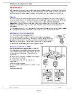
Page 17: ...y for any damage to the motor or any fire damage linked to inappropriate maintenance or failure to observe the above safety recommendations Maintenance of the Anti Grease Filters This filter traps cooking grease particles The grease filter must be cleaned once a month using non aggressive detergents either by hand or in the dishwasher which must be set to a low temperature and a short cycle When w...

Page 18: ...fore calling Technical Service If the hood is not working check that The power has not been disconnected A speed has been selected If the hood performs inefficiently check that The motor speed selected is sufficient for the amount of smoke and vapours released The kitchen is sufficiently ventilated to allow air intake The charcoal filter is not worn hood in filtering version If the hood has turned...

Page 19: ...IRING DIAGRAM Blue Blue Blue Yellow Yellow Black Red White Blue IEC Connector Micro Switch Push Button Blue Yellow Blue Blue Red Black White Brown Yellow Blue Blue Red Black White Brown Blue Brown Yellow Black Red White Grey Grey Grey Blue Blue Grey Brown SEL0060629 ...

Page 20: ...20 of 25 Service Manual UK Whirlpool UK Appliances Ltd English ITEMS SUPPLIED ...

Page 21: ...ic cover using a small screwdriver taking care not to scratch the surface of the hood itself Fig 1 b Unscrew the faulty lamp s It may be necessary to slide open the filter grille to give better access Replace the lamp with the same type and wattage c Reassemble in reverse order 2 Lamp Holder a Invert the hood and place upon a protected surface b Remove the grease filter and carbon filters if fitte...

Page 22: ...ocation and replace g Reassemble in reverse order 3 Motor Replacement a Invert the hood and place upon a protected surface b Remove the grease filter and carbon filters if fitted c Remove the lamp cover surround 2 screws T10 d Unscrew the lamps e Slide open the filter grille and remove the motor assembly fixing screws T20 and lift the motor assembly off the tabs continued ...

Page 23: ... Access to a motor cover securing tab should now be possible i Separate the two motor cover halves by releasing all the remaining tabs j Gently lift off the motor fixing nut covers by inserting a small screwdriver k Withdraw the fan assembly from the hood and remove the impeller by unscrewing the brass securing nut 12mm whilst keeping the impeller static noting the position of the fan on the motor...

Page 24: ...ce upon a protected surface b Remove the grease filter and carbon filters if fitted c If required the front panel with logo can be replaced by unscrewing the 2 securing screws d Remove the 4 screws T10 2 each side securing the slider assembly e Reassemble in reverse order It may be easier to first replace the 2 end screws with the slider closed this may aid balancing the assembly Continue then wit...

Page 25: ...ease filter and carbon filters if fitted c It is recommended to remove the slider assembly at this point 4 screws and also the lamp cover surround 2 screws T10 d Carefully unclip the surround for the buttons The buttons can now be pulled off if replacing is required e Slide the switch assembly out of the casing and release the motor plug f Reassemble in reverse order ...

Reviews: