Hotpoint HDM67G9C2CX/U Quick Manual Download Page 7

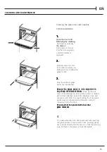
•remove the grids and slide the burners from their

housings;

• unscrew the nozzles

using a 7 mm socket
spanner, and replace
them with nozzles for
the new type of gas
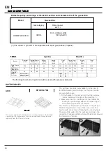
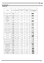
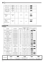
(see table 1 “Burner and
nozzle characteristics”).

•replace all the

components by
repeating the steps in
reverse order.

INSTALLATION TIPS

c )

c )

c )

c )

c )

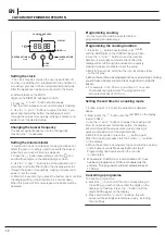
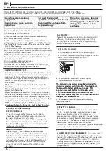
Minimum regulation of the hob burners:

• turn the tap to minimum;
• remove the knob and adjust

the regulation screw, which is
positioned in or next to the tap
pin, until the flame is small
but steady.

In the case of liquid gas, the regulation screw
must be adjusted to the minimum setting.

check that the flame does not turn off when

you turn the tap quickly from high to low.

d )

d )

d )

d )

d )

Regulating the primary air of the burners:

The primary air of the burners requires no regulation.

7

On completion of the operation, replace the old rating

sticker with one indicating the new type of gas used.

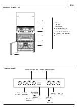
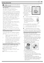
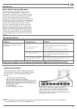
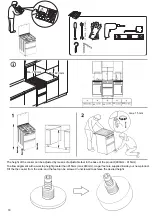
Replacing the Triple ring burner nozzles

1. Remove the pan supports and lift the burners out of 

their housing. The burner consists of two separate 
parts (see pictures).

2. Unscrew the nozzles using a 7 mm socket spanner. 

Replace the nozzles with models that are configured 
for use with the new type of gas (see Table 1). The 
two nozzles have the same hole diameter.

3. Replace all the components by completing the 

above operations in reverse order.

•  Adjusting the burners’ primary air :

Does not require adjusting.
•  Setting the burners to minimum:
1. Turn the tap to the low flame position.
2. Remove the knob and adjust the adjustment screw, 

which is positioned in or next to the tap pin, until the 
flame is small but steady.

3. Having adjusted the flame to the required low 

setting, while the burner is alight, quickly change the 
position of the knob from minimum to maximum and 
vice versa several times, checking that the flame 
does not go out.

EN

The cooker should be connected to the

gas-supply by a gas safe registered installer. 

Connection of the appliance to the gas
mains or liquid gas must be carried out according to
the prescribed regulation in force, and only after it is
ascertained that it is adaptable to the type of gas to

be used. If not, follow the instructions indicated in
the paragraph headed “Adaptation to different gas
types”. In the case of connection to liquid gas, by
tank, use pressure regulators that conform to the
regulation in force. The gas supply must be
connected to the left of the appliance. Be sure that
the hose does not pass through the rear of the
cooker touching hot parts.
Make sure the supply pressure conforms with the
values shown in the table entitled “Caracteristics of
the burners and nozzles”.
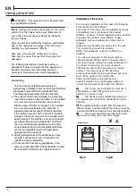
 When the cooker is installed between
cabinets (recessed), the gas connection
must be effected by an approved flexible
hose with bayonet fitting
(BS 669 or EN 14800). The gas inlet for
the cookers is a threaded G 1/2 gas female
f i t t i n g .

Connecting the gas supply

To make the connection, a flexible hose should be
used corresponding to the current gas regulations
which are:

the hose must never be at any point in its

lenght in contact with the “hot” parts

of the cooker;

the hose must never be longer than 1,5 metre;

the hose must not be subject to any tension

or torsional stress and it must not have any 

         excessively narrow curves or bottlenecks;

the hose must be easy to inspect along its

entire length to check its condition;

the hose must always be in good condition,

never attempt to repair.

Adapting the cooker to different types of gas

In order to adapt the cooker to a different type of
gas with respect to the gas for which it was
produced follow these steps:

a)

a)

a)

a)

a) replace the hose holder mounted on the
appliance with that supplied in the bag of “cooker
accessories”.

b)

b)

b)

b)

b) Replacing the burner nozzles on the hob:

WARNING : This operation must be perfomed

by a qualified technician

Gas connection

Summary of Contents for HDM67G9C2CX/U

Page 1: ...HDM67G9C2CX U HDM67G9C2CX U EN ENGLISH Health and Safety guide Installation guide Quick guide ...

Page 2: ...on safe use and understand the hazards involved Children must not play with the appliance Cleaning and user maintenance must notbecarriedoutbychildrenwithoutsupervision CAUTION In case of hotplate glass breakage shut immediately off all burners and any electrical heating element and isolate the appliance from the power supply do not touch the appliance surface do not use the appliance The glass li...

Page 3: ...ngs use for the ventilation and dispersion of heat must never be covered in certain models only We recommend the appliance should be handled and installed by two or more persons risk of injury Use protective gloves to unpack and install risk of GAS CONNECTION WARNING Prior to installation ensure that the local distribution conditions type of gas and gas pressure and the configuration of the applia...

Page 4: ...pull the power supply cable Do not use extension leads multiple sockets or adapters The electrical components must not be accessible to the user after installation Do not use the appliance when you are wet or barefoot Do not operate this appliance if it has a damaged power cable or plug if it is not working properly or if it has been damaged or dropped If the supply cord is damaged it must be repl...

Page 5: ...he level is indicated on the wall of the cooking compartment 6 Glass cover 1 2 2 Main oven door Removable Inner Door Glass 5 5 Gas burners 3 3 4 6 4 CONTROL PANEL Left rear hob burner Left front hob burner Right front hob burner Right rear hob burner Thermostat EN KNOB ICON KNOB ICON GRILL TOP OVEN SELECTOR TOP OVEN GRILL THERMOSTAT ...

Page 6: ...w or an acceptable alternative such as an adjustable louvre or hinged panel opening direct to outside air 6 EN This unit may be installed and used only in permanently ventilated rooms according to the British The following This unit may be installed and used only in permanently ventilated rooms according to the British Standards Codes Of Practice BS 5440 Part 2 requirements must be observed The fo...

Page 7: ...es not go out EN The cooker should be connected to the gas supply by a gas safe registered installer Connection of the appliance to the gas mains or liquid gas must be carried out according to the prescribed regulation in force and only after it is ascertained that it is adaptable to the type of gas to be used If not follow the instructions indicated in the paragraph headed Adaptation to different...

Page 8: ...ces to Prevent Leaks These models can be identified by the presence of the device itself Since the hob burners are equipped with a safety device you must hold the control knob in for about 3 7 seconds after the burner has been lighted to allow the gas to pass until the safety thermocouple has heated HOB GAS BURNER SAFETY DEVICE ELECTRONIC LIGHTING DEVICE HOTPLATE ELECTRICAL CONNECTION WARNING This...

Page 9: ...ersonal taste and requirements it may be necessary to increase or decrease temperatures by 10 C Unless otherwise indicated in the charts food should be placed in a cold oven i e without pre heating If food is placed in an already hot oven the suggested cooking time should be reduced depending on the type and quantity of food being cooked Oven positions Since the distribution of heat in the circula...

Page 10: ...able 1 Liquid Gas Natural Gas ACCESSORIES The grill pan handle is detachable from the pan to facilitate cleaning and storage Fix the pan handle securely before use 1 Fit the handle to the grill pan so that the external hooks embrace the edge of the pan fig 1 2 Make sure that the middle part of the handle fits exactly the protruding support of the pan fig 2 and holds the pan from the bottom The foo...

Page 11: ... main oven Fan Cooking Turn the control clockwise and select any temperature between 0 C and Max As the control is turned the fan will start The main oven light will immediately come on The thermostat light indicates that the main oven is heating When it turns off the temperature inside the oven has reached the setting made with the main oven knob At this point the light will turn on and off as th...

Page 12: ... through the values more quickly making it quicker and easier to set the value 3 Wait for 5 seconds after that the icon will be visible 4 When the set time has elapsed and the oven will stop cooking you will hear a buzzer sounds Press any button to stop the buzzer For example it is 9 00 a m and a time of 1 hour and 15 minutes is programmed The programme will stop automatically at 10 15 a m Setting...

Page 13: ...ll cakes Muffin FORCED AIR YES 150 160 30 50 2 5 Choux buns FORCED AIR YES 170 200 30 60 3 Choux buns FORCED AIR YES 170 200 20 50 Pizza Bread Focaccia FORCED AIR YES 190 250 15 50 2 Pizza Bread Focaccia FORCED AIR YES 190 230 20 50 2 4 Savoury pies vegetable pie quiche FORCED AIR YES 180 30 60 3 Vols au vent Puff pastry crackers FORCED AIR YES 180 210 15 40 3 Vols au vent Puff pastry crackers FOR...

Page 14: ...ish fillets Steaks GRILL 230 MAX 15 35 2 Vegetable gratin GRILL 230 MAX 10 30 2 Toast GRILL 5 MAX 0 5 1 5 2 Sausages Kebabs Spare ribs Hamburgers GRILL 230 MAX 15 30 Roast potatoes CONVENTIONAL YES 190 220 40 80 2 Vegetable gratin FORCED AIR YES 180 200 20 30 3 Stuffed vegetables tomatoes courgettes aubergines FORCED AIR YES 190 220 40 80 3 Complete meal Cook3 Fruit tart Lasagna Roast FORCED AIR 1...

Page 15: ...ft cloth For slight soiling the inner glass panel may be cleaned while still warm without removing it from the door glass removed To reassemble the oven doors proceed with inserting the glass panels in the reverse order pushing gently every panel directly into the liners so that the warning glass removed glass removed glass removed glass removed glass removed Oven must not be operated with inner d...

Page 16: ...s in a washing up liquid solution after use handling them with oven gloves if they are still hot Food residues can be removed using a washing up brush or a sponge REPLACING THE LIGHT 1 Disconnect the oven from the power supply 2 Unscrew the cover from the light replace the bulb and screw the cover back on the light Only in some models 3 Reconnect the oven to the power supply Note Use 40 W 230 V ty...

Page 17: ... for guidance and will depend on the amount of food and type of accessory used Use the lowest recommended settings to begin with and if the food is not cooked enough then switch to higher settings Use the accessories supplied and preferably dark coloured metal cake tins and baking trays You can also use Pyrex pans and accessories or ones made from china but bear in mind that cooking times will be ...

Page 18: ...adjusted by means of adjustable feet in the base of the product 900mm 915mm To allow alignment with a worktop height greater than 915mm max 940mm longer feet are supplied inside your new product Tilt the the cooker from the side and the feet can be screwed unscrewed to achieve the desired height ...

Page 19: ...if the requirements of BS 6172 2010 can still be met intended to prevent the appliance trapping the flexible hose If the flexible hose and it s rigid pipework connections are recessed Brown red Blue black Earth Connecting to gas supply Position the gas connection point such that it is located within the shaded area and the hose also hangs naturally within the shaded area Hot parts Installation are...

Page 20: ...XEROX FABRIANO www hotpoint co uk 20 W11517276 W11517276 06 2022 ...

Reviews: