16
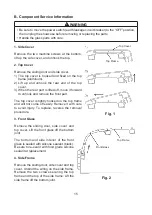
5. Center Frame (Except HNC-120 Type)
Remove the two flat head machine screws (black)
securing the center frame to the rear and the two
machine screws securing the center frame to the top
frame. Tilt the center frame and release it from the
joint.
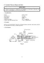
6. Holder - Evaporator Pipe
Remove the truss head tapping screw (4 x
30) from the bottom of the top frame. Take
off the center frame. Be careful with the
evaporator pipe. It will be released and hang
down. Remove the truss head tapping screw
(4 x 10) from the bottom of the top frame.
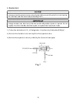
7. Refrigeration Assembly
IMPORTANT
Follow the instructions in “DANGER” and
“WARNING” for flammable refrigerant use
and “III. A. Refrigeration Circuit Service
Information”.
Remove the sliding door, side cover, top
cover, top frame and side frame. Take off the
compressor terminal cover and remove the
starter and motor protector. Uninsulate the
expansion valve and unbraze the outlet pipe
(see “C. Constant Pressure Expansion Valve”).
Unbraze the joint indicated. Remove the four
machine screws securing the refrigeration
assembly. The whole refrigeration assembly
can be pulled out.
Fig. 3
Fig. 4
Truss Head Tapping
Screw 4 x 30
Truss Head Tapping
Screw 4 x 10
Holder -
Evaporator Pipe
Evaporator Pipe
Fig. 5
Outlet Pipe
Joint
Expansion Valve
Summary of Contents for HNC-120BE-L-BH
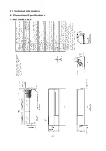
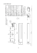
Page 22: ...21 VI Technical Information A Dimensions Specifications 1 HNC 120BE L BLH...
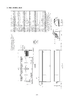
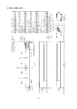
Page 23: ...22 2 HNC 150BE L BLH...
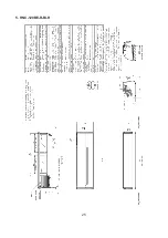
Page 24: ...23 3 HNC 180BE L BLH...
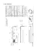
Page 25: ...24 4 HNC 210BE L BLH...
Page 26: ...25 5 HNC 120BE R BLH...
Page 27: ...26 6 HNC 150BE R BLH...
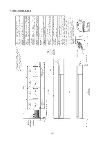
Page 28: ...27 7 HNC 180BE R BLH...
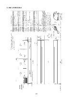
Page 29: ...28 8 HNC 210BE R BLH...
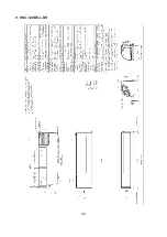
Page 30: ...29 9 HNC 120BE L BH...
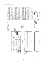
Page 31: ...30 10 HNC 150BE L BH...
Page 32: ...31 11 HNC 180BE L BH...
Page 33: ...32 12 HNC 210BE L BH...
Page 34: ...33 13 HNC 120BE R BH...
Page 35: ...34 14 HNC 150BE R BH...
Page 36: ...35 15 HNC 180BE R BH...
Page 37: ...36 16 HNC 210BE R BH...

