Hoshizaki HNC-120BA-L-S Service Manual Download Page 5

1

1. SAFETY INSTRUCTIONS

The following instructions contain important safety precautions and should be strictly 
observed. The terms used here are defined as follows:

     WARNING

:  There is a possibility of death or serious injury for the service person and 

a third party or the user due to improper service operations or defects in 
serviced products.

CAUTION

There is a possibility of injury for the service person and a third party or the 
user or damage to their property* due to improper service operations or 
defects in serviced products.

* The term “damage to their property” here refers to extensive damage to household 

effects, houses and pets.

WARNING

1. Always ask the user to keep children away from the work area. They may be injured by 

tools or disassembled products.

2. When there is no need to energize the unit during disassembly or cleaning, be sure to 

unplug the unit or disconnect the main power supply before servicing the unit to prevent 
electric shocks.

3. If the unit must be energized for inspection of the electric circuit, use rubber gloves to 

avoid contact with any live parts resulting in electric shocks.

4. Keep the following in mind when servicing the refrigeration circuit:

(1) Be sure to recover the refrigerant. Do not discharge it into the atmosphere. It will 

affect the environment.

(2) Check for any flames in the vicinity, and ensure good ventilation.

(3) If the refrigerant should leak in servicing, immediately put out any fire used in the 

vicinity.

(4) When unbrazing the refrigeration circuit connections, check that the circuit is 

completely evacuated. The refrigerant may produce a poisonous gas when coming 
in contact with an open flame.

(5) Do not braze in an enclosed room to prevent carbon monoxide poisoning.

(6) In case of a refrigerant leak, locate and repair the leaking part completely. Leaked 

refrigerant may produce a poisonous gas when coming in contact with an open 
flame.

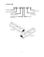
Summary of Contents for HNC-120BA-L-S

Page 1: ...NO S041 789 ISSUED OCT 26 2009 REVISED HOSHIZAKI COUNTER SHOWCASE SERVICE MANUAL MODEL HNC 120BA L R S HNC 150BA L R S HNC 180BA L R S HNC 210BA L R S...

Page 2: ...ce of the product Should the reader have any questions or concerns which have not been satisfactorily addressed please call write or send an e mail message to the Hoshizaki Technical Support Departmen...

Page 3: ...r reference that may be necessary CONTENTS PAGE 1 SAFETY INSTRUCTIONS 1 2 MODEL NAME 3 3 OPERATING INSTRUCTIONS 4 4 SPECIFICATIONS 5 5 DIMENSIONS 6 a HNC 120BA L S 6 b HNC 120BA R S 7 c HNC 150BA L S...

Page 4: ...11 CONSTANT PRESSURE EXPANSION VALVE AND REFRIGERANT CHARGE 20 a SPECIFICATIONS 20 b FUNCTION 20 c CONSTRUCTION 20 d REPLACEMENT 21 12 SERVICE DIAGNOSIS 22 ii...

Page 5: ...be sure to unplug the unit or disconnect the main power supply before servicing the unit to prevent electric shocks 3 If the unit must be energized for inspection of the electric circuit use rubber g...

Page 6: ...connectors or the like with their closed ends up to avoid entrance of moisture that could lead to electric leaks or re 6 After servicing always use a megohmmeter 500V DC to check for the insulation re...

Page 7: ...E H NC 120 B A L R S High Grade Exterior S Stainless steel Counter Showcase Unit Location Width cm L Unit on left 120 150 180 210 R Unit on right Development Order HA model Starts from A Unit on right...

Page 8: ...ay rise resulting in food deterioration 4 Do not pack the showcase with foods The cooling performance may reduce resulting in food deterioration 5 The showcase should not be exposed to direct sunlight...

Page 9: ...R D04763 L D04764 R D04765 L D04766 R D04767 L D04768 R D04769 REFRIGERATION SYSTEM DEFROST SYSTEM Convection Cooling None Hermetic 130W Model CE56Y 1ZU Fin and Tube Type Cooling Fan Motor x 1 UPPER...

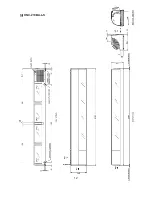
Page 10: ...6 5 DIMENSIONS a HNC 120BA L S...

Page 11: ...7 b HNC 120BA R S...

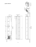
Page 12: ...8 c HNC 150BA L S...

Page 13: ...9 d HNC 150BA R S...

Page 14: ...10 e HNC 180BA L S...

Page 15: ...11 f HNC 180BA R S...

Page 16: ...12 g HNC 210BA L S...

Page 17: ...13 h HNC 210BA R S...

Page 18: ...14 6 REFRIGERATION CIRCUIT Refrigerant R134a Heat Exchange Condenser Drier Expansion Valve Evaporator Upper Evaporator Lower Fan Motor Compressor...

Page 19: ...15 7 WIRING DIAGRAM CM Compressor SR Start Relay SC Start Capacitor OL Overload Relay FM Fan Motor ELB Ground Fault Circuit Interrupter Power Supply 1 phase 115V 60Hz BK W BK W BU...

Page 20: ...16 8 CONSTRUCTION Top Cover Nameplate Joint Hose Front Glass Plug Power Switch Ground Fault Interrupter Condenser Center Frame Air Filter Slider Louver Sliding Glass Door Food Mount...

Page 21: ...r is hooked and xed on the top frame aluminum 2 Lift up and unhook the rear end of the top cover 3 When the rear part is lifted off move it forward to unhook and remove the front part The top cover is...

Page 22: ...nd release it from the t f HOLDER EVAPORATOR PIPE Remove the truss head tapping screw 4 x 25 from the bottom of the top frame Take off the center frame Be careful with the evaporator pipe It will be r...

Page 23: ...the same handy ux that has been used for the current refrigerants However its entrance into the refrigerant circuit should be avoided as much as possible 4 Oil for Processing of Copper Tubing R134a Wh...

Page 24: ...re may cause R134a to suddenly react with oxygen and explode Be sure to use nitrogen to prevent explosion 11 CONSTANT PRESSURE EXPANSION VALVE AND REFRIGERANT CHARGE a SPECIFICATIONS Model HYP 2 5QHD...

Page 25: ...r every time the sealed refrigeration system is opened Do not replace the Drier until after all other repairs or replacement have been made 1 Recover the refrigerant R134a and store it in an approved...

Page 26: ...or air lter clogged 3 Clean 4 Condenser air inlet blocked 4 9 Instruct the user on characteristics and proper use of the showcase 5 Exposed to direct sunlight 6 Located next to a high heat producing...

Reviews: