Hoshizaki F-300BAJ Service Manual Download Page 23

23

D. Bin Control Check

Bin Control Check

When the actuator paddle is not engaged BC is closed and the icemaker produces ice. 
With CB S1 dip switch 7 placed in the "OFF" position, BC is used as a stand-alone bin 
control. The stand-alone application should only be used in standard ice storage bin 
applications. When ice fills the chute and engages the actuator paddle, BC opens and 
CB starts the 150-sec. shutdown sequence.

1) Remove the front panel and move the power switch to the "OFF" position, then unplug 

the appliance from the electrical outlet (F-300BAJ) or turn the power supply off 
(F-500BAJ). 

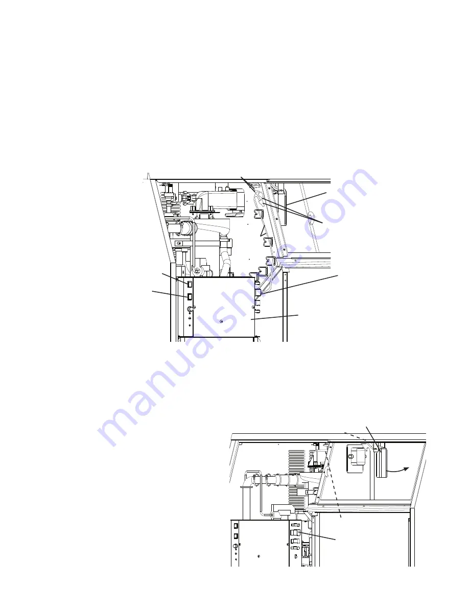
2) Disconnect the 12 pin connector from the control box or disconnect the bell connectors. 

See Fig. 2.

Fig. 2

Fig. 3

3) Open the ice storage bin door so that you can access the actuator paddle located in the 

top of the bin. See Fig. 3.

4) With actuator paddle not engaged, check for continuity across BC GY wires (proximity 

switch) in 12 pin connector plug or black (BK) wires from bell connectors. BC closed. 
If BC continuity indicates open BC with the actuator paddle engaged, replace BC 
(proximity switch).

5) Press the actuator paddle located 

in the top of the bin to the right 
(actuator paddle engaged). Check 
for continuity across BC GY 
wires (proximity switch) in 12 pin 
connector plug or black (BK) wires 
from bell connectors. BC open. 
If BC continuity indicates closed BC 
with the actuator paddle engaged, 
replace BC (proximity switch). 

Actuator Paddle

Bell Connectors

12 Pin Connector

Control Box

Control Switch

Powerl Switch

12 Pin Connector

Actuator Paddle

Bell Connectors

Proximity Switch

GY Wire

BK Wire

Model Shown: F-300BAJ

Model Shown: F-300BAJ

Summary of Contents for F-300BAJ

Page 1: ...Models F 300BAJ F 500BAJ Self Contained Flaker Service Manual Number 73214 Issued 1 30 2017 hoshizakiamerica com...

Page 2: ...rty damage due to improper installation is not covered under warranty Hoshizaki provides this manual primarily to assist qualified service technicians in the service of the appliance Should the reader...

Page 3: ...4 Continuous Dispensing Timer S1 dip switch 5 6 33 5 Bin Control Selector S1 dip switch 7 34 6 Agitation and Ice Purge Timer S1 dip switch 8 34 7 Mechanical Shutdown Delay S1 dip switch 9 34 8 Factory...

Page 4: ...anty coverage and may result in costly water damage To reduce the risk of death electric shock serious injury or fire follow basic precautions including the following Only qualified service technician...

Page 5: ...replace the power cord be sure to connect the power cord s ground wire For Hard Wired Models Electrical connection must be hard wired Before servicing move the power switch to the OFF position Turn of...

Page 6: ...fully to reduce the risk of costly water damage In areas where water damage is a concern install in a contained area with a floor drain Install the appliance in a location that stays above freezing No...

Page 7: ...Water Refrigeration Circuit Diagram A Construction 1 F 300BAJ Ice Storage Bin Inlet Water Valve Reservoir Control Box Bin Control The actuator is located in the ice storage bin Spout Evaporator Gear M...

Page 8: ...8 2 F 500BAJ Ice Storage Bin Inlet Water Valve Reservoir Control Box Bin Control The actuator is located in the ice storage bin Spout Evaporator Gear Motor Compressor Front...

Page 9: ...BAJ and F 500BAJ Seal Bolt Gear Motor Spline Coupling Housing Lower Bearing O Ring Mechanical Seal Cylinder Auger Extruding Head Upper Bearing Cutter Insulation Socket Head Cap Screw with Split Lock W...

Page 10: ...igh Pressure Switch Compressor Overflow Hose Reservoir Drain Valve Thermostatic Expansion Valve Spout Water Level Evaporator Float Switch Inlet Water Valve Water Supply Line Gear Motor Drain Pan Evapo...

Page 11: ...cle starts FT Maximum 90 sec 4 1 in 12 Drain Cycle Although the factory default 1 in 1 drain cycle is recommended a 1 in 12 drain cycle is available For 1 in 12 drain cycle sequence see 3 1 in 12 Hour...

Page 12: ...oat switch PT purge timer UFS upper float switch WV inlet water valve to 2 Ice Purge Cycle above if UFS closed to 1 Fill Cycle above if UFS open 1 Bin Full GM energized Comp de energized FM de energiz...

Page 13: ...Make sure that none have fallen into the ice storage bin Make sure all food zones in the icemaker and ice storage bin are clean after service 1 Ice Production Check To check production prepare a buck...

Page 14: ...hould be taken not to touch live terminals If the icemaker is in alarm see III A 2 LED Lights and Audible Alarm Safeties CB monitors the following switches with 5VDC during the icemaking process Contr...

Page 15: ...rvoir is empty and LFS and UFS are open 90 sec FT starts WV energizes and fill cycle starts LFS closes Nothing occurs at this time Reservoir continues to fill until UFS closes When UFS closes WV de en...

Page 16: ...ZT terminates and FT starts FZT 30 Min Freeze Safety Timer FZT starts when UFS closes and terminates when LFS opens If LFS does not open within 30 min of UFS closing CB shuts down the icemaker and sou...

Page 17: ...t on CB K2 8 O replace CB If 24VAC is present on CB K2 8 O check continuity through WV solenoid If open replace WV If WV is energized and refill exceeds FT with no water in the reservoir check for DV...

Page 18: ...M de energize and the 5 min ice purge timer begins When the 5 min ice purge timer terminates GM and CCR de energize DV energizes to drain the evaporator and reservoir To avoid the 5 min shutdown delay...

Page 19: ...from the control transformer and that the fuse is good Check for 24VAC at CB K8 1 W R to CB K8 2 LBU If 24VAC is present and the POWER OK LED is off replace CB 3 5VDC Output Checks CB K9 Connector Co...

Page 20: ...continuity across the high pressure switch CB K9 3 Y and CB K9 4 Y c Compressor Control Relay CCR CB K9 5 W O and CB K9 6 W O 5VDC is present from CB white K5 connector pin closest to CB red K4 conne...

Page 21: ...ED is on and GM and CCR are off check for 115VAC from CB K1 2 BK to a neutral W If 115VAC is not present check 115VAC power supply connections from power switch If 115VAC is present check for 115VAC f...

Page 22: ...5 black 5VDC S1 Dip Switch K8 Connector 24VAC and 5VDC K7 Connector Open K2 Connector 24VAC 5VDC common terminals K3 Connector Open K4 Connector Open K5 Connector Open Inlet Water Valve 8 O 3 2 1 DRA...

Page 23: ...he ice storage bin door so that you can access the actuator paddle located in the top of the bin See Fig 3 4 With actuator paddle not engaged check for continuity across BC GY wires proximity switch i...

Page 24: ...should be taken not to touch live terminals COMP LED turns on 9 Press the actuator paddle located in the top of the bin to the right actuator paddle engaged See Fig 4 The 90 sec Comp shutdown timer st...

Page 25: ...en If open continue to step 5 If closed follow the steps in II E 2 Float Switch Cleaning After cleaning the floats check them again Replace if necessary 5 Reconnect the FS molex plug on the control bo...

Page 26: ...h a mixture of 1 part Hoshizaki Scale Away and 25 parts warm water 5 While not necessary the floats can be removed from the shaft during cleaning If you remove them note that the blue float is on top...

Page 27: ...5 Fuse 3A a Blown 6 Bin Control See II D Bin Control Check a Open b Defective 7 Control Switch a In DRAIN position b Defective 8 Compressor Control Relay a Defective 9 Evaporator Heater C model a Defe...

Page 28: ...l a Defective Refill 1 Float Switch See II E Float Switch Check and Cleaning a Dirty sticking b Defective 2 Inlet Water Valve a Screen or orifice clogged b Defective 3 Water Supply a Water supply off...

Page 29: ...ntains integrated circuits which are susceptible to failure due to static discharge It is especially important to touch the metal part of the icemaker when handling or replacing the control board Do n...

Page 30: ...lack 5VDC S1 Dip Switch K8 Connector 24VAC and 5VDC K7 Connector Open K2 Connector 24VAC 5VDC common terminals K3 Connector Open K4 Connector Open K5 Connector Open Inlet Water Valve 8 O 3 2 1 DRAIN J...

Page 31: ...threshold and the high pressure switch closes 4 High Pressure Switch Third activation in 1 hour Call for service To avoid possible catastrophic failure it is recommended to leave the icemaker off unt...

Page 32: ...lt Dip Switch Settings The S1 dip switch settings are factory set to the following positions Dip Switch No 1 2 3 4 5 6 7 8 9 10 F 300BAJ F 500BAJ OFF OFF OFF OFF OFF OFF OFF ON OFF OFF infrared sensor...

Page 33: ...down Delay No 1 No 2 No 3 OFF OFF OFF 0 Seconds ON OFF OFF 100 Seconds 1 6 minutes Factory Default OFF ON OFF 1100 Seconds 18 3 minutes OFF OFF ON 1650 Seconds 27 5 minutes ON ON OFF 2200 Seconds 36 7...

Page 34: ...6 Agitation and Ice Purge Timer S1 dip switch 8 Not available when S1 dip switch 7 is on Factory set for normal operation No adjustment is required WARNING Do not adjust S1 dip switch 8 out of the fac...

Page 35: ...trol switch for unit operation 2 Control Switch The control switch has 2 positions ICE and DRAIN When the control switch is in the ICE position open icemaking begins When the control switch is in the...

Page 36: ...t to the system if using an electronic leak detector and then raise the pressure using nitrogen gas 140 PSIG Do not use R 404A as a mixture with pressurized air for leak testing NOTICE Always recover...

Page 37: ...g an electronic leak detector and then raise the pressure using nitrogen gas 140 PSIG Do not use R 404A as a mixture with pressurized air for leak testing 3 Evacuation and Recharge R 404A 1 Attach a v...

Page 38: ...the system to charge with liquid until the proper charge weight is met 8 If necessary add any remaining charge to the system through the low side NOTICE To prevent compressor damage use a throttling v...

Page 39: ...to the torque value listed below Torque for F 300BAJ and F 500BAJ 11 1 ft lb 15 N m Tighten 2 times Allow at least 5 sec in between each tightening Component Notes Compressor Install a new drier start...

Page 40: ...r Evaporator Flange Evaporator Assembly Flaker Cutter Flaker Extruding Head Evaporator Socket Head Cap Screw and Split Lock Washer Upper Bearing pressed into extruding head Fig 5 Packing Seal Bolts In...

Page 41: ...the lower bearing in the housing should be replaced Instructions for removing the extruding head and housing are located later in this procedure Note Replacing the bearing requires a bearing press ada...

Page 42: ...he DRAIN position c Move the power switch to the ON position and allow the water to drain from the evaporator d Move the power switch to the OFF position then unplug the appliance F 300BAJ or turn off...

Page 43: ...tions 9 Move the control switch to the ICE position 10 Move the power switch to the ON position 11 Replace the front panel in its correct position then plug the appliance into the electrical outlet F...

Page 44: ...t a pressure of 3 to 4 PSIG 15 Use an electronic leak detector or soap bubbles to check for leaks Add a trace of refrigerant to the system if using an electronic leak detector and then raise the press...

Page 45: ...lower housing 8 Remove the O ring and mechanical seal from the housing If only replacing the mechanical seal proceed to step 11 NOTICE To help prevent water leaks be careful not to damage the surfaces...

Page 46: ...0BAJ 2 Remove the top and side panels 3 Remove the strap connecting the spout to the chute assembly then remove the spout 4 Remove the hex head bolts and washers securing the lower housing to the gear...

Page 47: ...k do not touch the icemaker power switch or control switch with damp hands Before Servicing Move the icemaker s power switch to the OFF position Turn off the power supply Place the disconnect if appli...

Page 48: ...pans Repeat with a cup of clean water to rinse Icemaker and Ice Storage Bin Drains Check to make sure they are clear Extruding Head Seal Bolts Inspect for leakage around seal bolts Tighten see torque...

Page 49: ...osal The appliance contains refrigerant and must be disposed of in accordance with applicable national state and local codes and regulations Refrigerant must be recovered by properly certified service...

Page 50: ...9 131 273 124 90 32 258 117 247 112 230 104 lbs day kg day 100 38 217 99 205 93 188 85 APPROXIMATE ELECTRIC 70 21 586 592 598 CONSUMPTION 80 26 604 610 616 90 32 621 627 646 watts 100 38 665 683 702 A...

Page 51: ...191 379 172 lbs day kg day 100 38 361 164 344 156 305 138 APPROXIMATE ELECTRIC 70 21 808 816 823 CONSUMPTION 80 26 831 838 846 90 32 853 861 878 watts 100 38 895 913 930 APPROXIMATE WATER 70 21 64 24...

Page 52: ...52 B Wiring Diagrams 1 F 300BAJ High Pressure Switch Cut out 426 22 PSIG Cut in 341 22 PSIG 0...

Page 53: ...53 High Pressure Switch Cut out 426 22 PSIG Cut in 341 22 PSIG 0 2 F 500BAJ...

Reviews: