

2
3
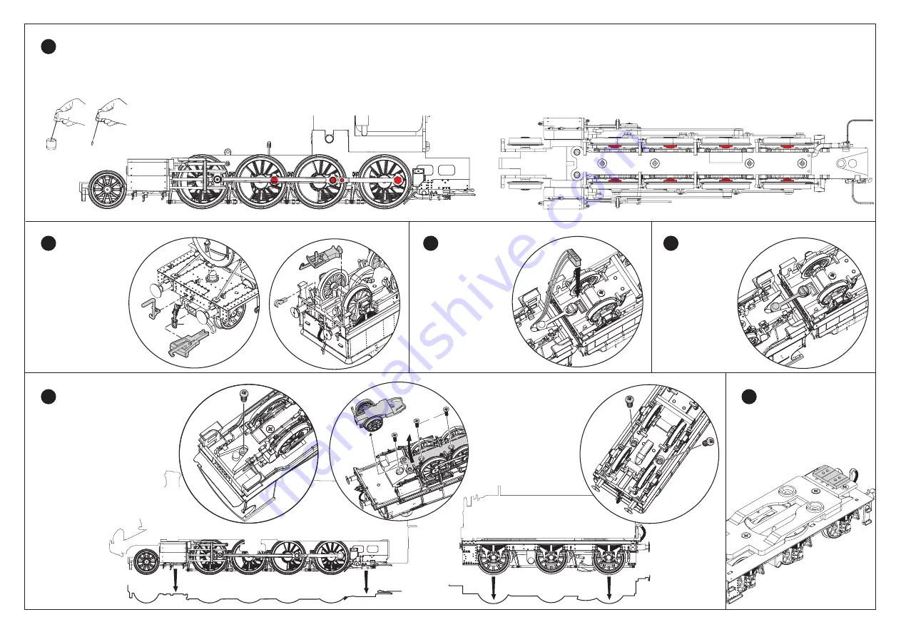
Lubrication
1
Fig.1
IMPORTANT – Only apply small single drops of light machine oil to the places indicated in red in Figs 2 and 3. This is best achieved by making a simple oil ‘dropper’ as illustrated in Fig.1. Insert a straightened paper clip into a cork and use a
bottle cap as a container for the oil. A small drop of oil can then be picked up by the dropper and applied in exactly the right place. Immediately wipe off any excess oil, especially from the locomotive body. Only lubricate moving parts.
Fig.3
Apply one drop of oil to each of the axle bearings indicated in red in
Fig.3.
If your locomotive is not
pre-fitted with a decoder,
please see Fig.13. for
location of DCC socket.
Fig.2
Apply one drop of oil to each of the valve gear and connecting rod
pivot points indicated in red in Fig.2, on both sides of the locomotive.
Carefully fit the
detailed parts into
their location points
(see Figs 4 and 5)
Some of these
accessories should
only be fitted for use
on static displays.
Accessories
2
Once the tender is coupled
to the loco, connect the
locomotive wires by
carefully push fitting the
plug into the socket on
the underside of the
tender as shown in Fig.6.
Assembly
3
Close coupling
4
Fig.6
Fig.5
Fig.7
To create a closer
coupling for display
purposes connect
the tender to the
locomotive by
utilising the closer
of the two holes
on the draw bar as
shown in Fig.7.
Body Removal
Fig.12
Fig.8
Fig.10
Fig.9
Fig.11
5
Please keep the
screws safe for
re-assembly.
DCC Ready
6
Fig.13
Turn the locomotive upside down
and remove the first assembly screw
as shown in Fig.8. Then remove 2
srews from the base of the chassis
plate (Fig.9 no1) ease the end
upwards(Fig.9 no2) to allow removal
of front bogie (Fig.9 no3). Remove
the assembly screw underneath the
front bogie (Fig.9 no4). Carefully turn
locomotive the right way up and ease
the chassis down, gently pulling in a
vertical motion (Fig.10).
Fig.4
OR
EITHER
Turn the tender upside down,
remove the two assembly screws
as shown in Fig.11. Carefully
turn tender the right way up
and ease the chassis down,
gently pulling down in a
vertical motion (Fig.12).
3
2
1
4
Fig.12


