background image

7

EN

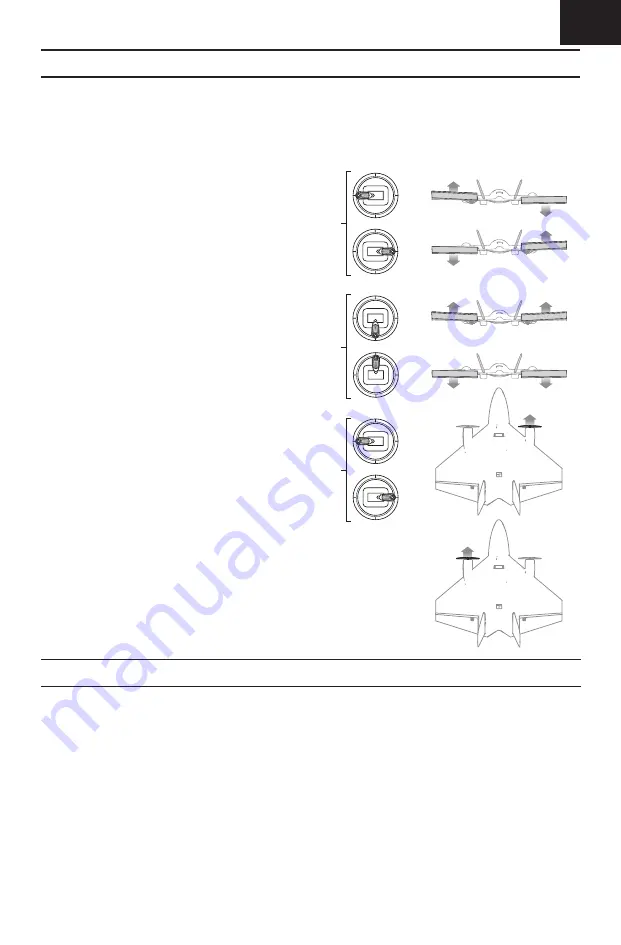
Control Direction Test

Properly bind your aircraft and transmitter before 
doing these tests. Verify the linkages move freely.
Switch ON the transmitter and connect the 
battery. Use the transmitter to operate the aileron 
and elevator controls. View the aircraft from the 
rear when checking the control directions.

Ailerons

1.  Move the aileron stick to the left. The right 

elevon should move down and the left elevon 
up, which will cause the aircraft to bank left 
in fl ight.

2.  Move the aileron stick to the right. The right 

elevon should move up and the left elevon 
down, which will cause the aircraft to bank 
right in fl ight.

Elevators

3.  Pull the elevator stick back. The elevons 

should move up, which will cause the aircraft 
to pitch up in fl ight.

4.  Push the elevator stick forward. The elevonsv 

should move down, which will cause the 
aircraft to pitch down in fl ight.

Rudder/ Differential Thrust

5.  Move the rudder stick to the left. The right 

motor will accelerate, which will cause the 
aircraft to yaw left in fl ight.

6.  Move the rudder stick to the right. The left 

motor will accelerate, which will cause the 
aircraft to yaw right in fl ight.

Tip:

 The motors will not accelerate with 

rudder input when the throttle is in the OFF 
position.

Aileron stick

Elevator stick

Rudder stick

This aircraft includes Spektrum SMART Technology in the 
receiver, which can provide telemetry information like 
battery voltage. To take advantage of SMART Technology, 
you will need a compatible transmitter. A fi rmware update 
for your transmitter may be required.

To View SMART Telemetry:

1.  Begin with the transmitter bound to the receiver
2.  Power on the transmitter.
3.  Power on the aircraft.
4.  The SMART Logo appears under the battery logo on 

the home page. A signal bar appears in the top left 
corner of the screen. 

5.  Scroll past the servo monitor to view SMART 

technology screens. 

For more information about compatible transmitters, 
fi rmware updates, and how to use the SMART Technology 
on your transmitter, visit www.SpektrumRC.com.

SMART Technology Telemetry

Summary of Contents for UMX Ultrix

Page 1: ...Instruction Manual Bedienungsanleitung Manuel d utilisation Manuale di Istruzioni SAFE Select Technology Optional Flight Envelope Protection UMX Ultrix...

Page 2: ...to compatibility and performance of counterfeit products or products claiming compatibility with DSM or Spektrum technology Age Recommendation Not for children under 14 years This is not a toy Safety...

Page 3: ...Flying Tips and Repairs 8 Post Flight Checklist 9 Service of Power Components 9 Replacement Parts List 9 Recommended Parts List 10 Optional Parts 10 AS3X Troubleshooting Guide 10 Troubleshooting Guide...

Page 4: ...rottle cut before approaching the aircraft IMPORTANT The Ultrix DOES NOT need elevon mixing The elevon mixing is handled in the receiver Dual Rates Flight modes and dual rates expo should be on the sa...

Page 5: ...d Low Voltage Cutoff Red Flashing Binding Procedure 1 Refer to your transmitter manual for instruction on binding the transmitter to a receiver 2 Ensure the ight battery is not connected to the aircra...

Page 6: ...battery and connect it to the ESC Slide battery to nose Keep plane immobile upright and away from wind for 5 seconds A series of tones indicates aircraft is armed and ready Before the rst ights or in...

Page 7: ...ck to the left The right motor will accelerate which will cause the aircraft to yaw left in ight 6 Move the rudder stick to the right The left motor will accelerate which will cause the aircraft to ya...

Page 8: ...d just above 1 2 throttle After the ESC stops the motor fully lower the throttle to re arm the ESC Repairs Crash damage is not covered under warranty Repair this aircraft using foam compatible CA glue...

Page 9: ...ble in reverse order connecting the motor covers to the wing with clear tape B A A B C F F B E G D B B B B B B E Front View Propeller direction Replacement Parts List Post Flight Checklist 1 Disconnec...

Page 10: ...rom factory Center control surfaces mechanically by adjusting the U bends on control linkages Aircraft was moved after the ight battery was connected and before sensors initialized Disconnect and reco...

Page 11: ...transmitter after binding Less than a 5 second wait between rst powering on transmitter and connecting ight battery to aircraft Leaving transmitter on disconnect and reconnect ight battery to aircraf...

Page 12: ...t that you may need any assistance For questions or assistance please visit our website at www horizonhobby com submit a Product Support Inquiry or call the toll free telephone number referenced in th...

Page 13: ...nd to be compliant with the applicable regulations governing a radio transmitter in the 2 400GHz to 2 4835GHz frequency range Supplier s Declaration of Conformity Ultrix BNF Basic SAFE EFLU6450 This d...

Page 14: ...t it is recycled in a manner that protects human health and the environment For more information about where you can drop off your waste equipment for recycling please contact your local city of ce yo...

Page 15: ...d trademarks of Horizon Hobby LLC The Spektrum trademark is used with permission of Bachmann Industries Inc All other trademarks service marks and logos are property of their respective owners US 8 67...

Reviews: