background image


8


• Use a pressure regulator to control the fuel inlet pressure to the system. 

• Do not alter the fitting on a regulator. Ask experienced personnel for help. 

• Do not attempt to force gas cylinder threads. 

• Never transport a gas cylinder with regulators attached. Ensure cylinder caps 

are in place. Always use a cylinder cart with a safety strap or chain. 

• Secure a high-pressure cylinder to a bench, post, or fixed object to avoid 

accidental contact. 

• Avoid unnecessary contact with On/Off valves. They can easily move to “On” by 

accident. 


1.4 Hydrogen Leakage 

Hydrogen is colorless, odorless and tasteless. Hydrogen is non-toxic but can act 

as a simple asphyxiated by displacing the oxygen in the air. There are no warning 

symptoms before unconsciousness results. 


WARNING! 
Inhaling hydrogen can lead to unconsciousness and asphyxiation.

Hydrogen molecules are smaller than any other gas, making hydrogen more 

difficult to contain. It can diffuse through many materials considered airtight. Fuel 

lines, non-welded connections, and non-metal seals such as gaskets, O-rings, 

pipe thread compounds and packings present potential leakage or permeation 

sites. Furthermore, hydrogen’s small molecule size results in high buoyancy and 

diffusivity, so leaked hydrogen will rise and become diluted quickly. 


Constant exposure to hydrogen causes hydrogen embrittlement in many 

materials. The mechanisms that cause hydrogen embrittlement effects are not 

well defined. Factors known to influence the rate and severity of hydrogen 

embrittlement include hydrogen concentration, hydrogen pressure, temperature, 

hydrogen purity, type of impurity, stress level, stress rate, metal composition, 

metal tensile strength, grain size, microstructure and heat treatment history. 

Moisture content in the hydrogen gas may lead to metal embrittlement through the 

acceleration of the formation of fatigue cracks. Hydrogen embrittlement can lead 

to leakage or catastrophic failures in metal and non-metallic components. 


As a preventative measure, H-1000XP must be operated in a well-ventilated area 

in order to inhibit potential hydrogen accumulation. 


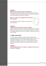
WARNING! 
Always operate H-1000XP in a well-ventilated area and ensure that 
ventilation slots are unobstructed. 

Summary of Contents for H-1000XP

Page 1: ...1 Date 2013 08 05 Part Number H 1000XP Version 20130805 Manual H 1000XP Fuel Cell System User ...

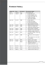
Page 2: ... 98 02 25 11 WRP 1 Modified Software Installation Rev 0 99 03 29 11 WRP 1 Added H2 sensor external power 2 Added fuse usage to Step 7 11 Rev 0 99 05 11 11 WRP 1 Fix mistake of supply purge valve direction arrow Rev 0 10 05 23 11 WRP 1 Add note for not too long purge line 2 Add warning for not to turn off by error protection Rev 0 11 11 11 11 WRP 1 Modify H2 sensor related Rev 0 12 12 05 02 Jason 1...

Page 3: ...priately tamper with the fuel cell Operate the fuel cell with a controller not designed and built by Horizon for the specific fuel cell Operate the fuel cell with valves and blowers that are not provided by Horizon for the specified fuel cell and controller Disassemble the fuel cell Disassemble the controller Operating the fuel cell and controller that is no that is not in the setup and or specifi...

Page 4: ...4 Table of Content 1 0 Safety 6 2 0 Part list 12 3 0 General information 18 4 0 System set up 27 5 0 Software 42 6 0 Maintenance 47 7 0 Troubleshooting 50 ...

Page 5: ... by which the electricity will be generated Humidification A process to humidify the proton exchange membranes for optimal performance Blower Fans attached to fuel cell stack to supply cooling air and process air Purging valve Excess water and hydrogen will be dispelled from the fuel cell flow channels via purge valve SCU Short circuit unit the short circuit will be controlled for good performance...

Page 6: ...6 1 0 SAFETY ...

Page 7: ...ignition away from hydrogen This unit uses hydrogen fuel Hydrogen is a colorless odorless and flammable substance It is highly combustible in the presence of oxygen and burns with a colorless flame Leaking gas may be hot and pose a burn danger Stop the flow of gas if you are not in danger and use water to cool the area If fire occurs do not attempt to extinguish flames allow the fire to burn out P...

Page 8: ...ctions and non metal seals such as gaskets O rings pipe thread compounds and packings present potential leakage or permeation sites Furthermore hydrogen s small molecule size results in high buoyancy and diffusivity so leaked hydrogen will rise and become diluted quickly Constant exposure to hydrogen causes hydrogen embrittlement in many materials The mechanisms that cause hydrogen embrittlement e...

Page 9: ... carry further WARNING A mixture of hydrogen and air is potentially flammable and explosive and can be ignited by a spark or a hot surface As in the presence of any fuel all sources of ignition including smoking are not permitted in the vicinity of the system WARNING Keep all sources of ignition away Smoking is not permitted in the vicinity of the H 1000XP 1 6 Oxygen Depletion Oxygen is a colorles...

Page 10: ...imize conductivity Avoid contact with surfaces that are in contact with water or gases Do not operate or store in wet or damp conditions Never use damaged extension cords H 1000XP generates up to 48 VDC open circuit voltage This voltage decreases as current is drawn from the module This voltage is exposed at the output power connections These low voltages may constitute a shock hazard and can dama...

Page 11: ...elets and watches may concentrate an electric current when it comes into contact with charged components or when a shock passes through the human body Accordingly no jewellery should be worn near H 1000XP 1 9 High Temperature The fuel cell stack is designed to operate above 60ºC sometimes At this operating temperature the air exhaust stream temperature can reach 55ºC and the cooling air stream can...

Page 12: ...12 2 0 PART LIST ...

Page 13: ...ck holder It helps to fix the fuel cell stack on the place you want There are 4 in the package As showed on stack picture above each side left or right can place 2 NOTE Please use bolts provided together with spring washer Do not over tighten The use of wrong screw length will damage the stack With innovative materials the H 1000XP achieved 1000W power output with more efficiency comparing to stan...

Page 14: ...n off For SCU Please refer to Terminology It is the connector which connect startup ba ery to the controller 8 Start up battery connector 6 LCD display It displays the system status current voltage temperature etc Please refer to trouble shooting section for more details Power supply for hydrogen sensor Please attached this wire to your on board battery 12V to power the hydrogen sensor ...

Page 15: ...e maximum voltage of the fuel cell is 48V so size your ultra capacitors accordingly 11 Ultra capacitor bank Optional The DC DC will regulate the output voltage for the controller It can step down the stack voltage 27 5V to 48V to 12V for the fuel cell controller and other peripheral parts 10 DC DC converter Optional 9 Ambient temperature sensor It senses the ambient temperature The sensor should b...

Page 16: ...tack and all peripheral parts to perform at its optimal condition It has the following features Control Stack temperature Control Stack purge rate Monitoring stack current and voltage Monitoring H2 concentration H2 sensor needed Protect stack from possible failures like stack low voltage over current over temperature Control Hydrogen supply and shut off RS232 Communication with computer 13 System ...

Page 17: ...ack Temperature Sensor Grey 3 4 Ambient Temperature Sensor Red Black 5 6 Blowers Red 5 ve Black 6 ve Black 7 8 Hydrogen Purge Valve Black 7 ve Black 8 ve Yellow 9 10 Hydrogen Supply Valve Yellow 9 ve Yellow 10 ve Blue 11 12 Short Circuit Switch Red Black 13 14 N A Black 15 N A Black 16 Blower PWM Table 2 1 Controller Connector ...

Page 18: ...18 3 0 GENERAL INFORMATION ...

Page 19: ...19 3 0 GENERAL INFORMATION 3 0 GENERAL INFORMATION Figure 3 1 1 Views and dimensions of H 1000XP stack Figure3 1 2 Views and dimensions of controller 3 1 Dimensions 264 203 213 264 79 104 203 79 114 ...

Page 20: ...v C D Fuel r i A d n a n e g o r d y H s t n a t c a e R 2 H y r d 9 9 9 9 n o i t i s o p m o C I S P 4 9 2 7 e r u s s e r p 2 H Hydrogen consumption 1000W or flowrate 12 5SLPM operation External temperature 5 35 C C 5 6 e r u t a r e p m e t k c a t s x a M Humidification Self humidified r i a g n i l o o C Relative humidity 10 95 RH non condensing V 2 1 y r e t t a b p u t r a t S Monitoring R...

Page 21: ...21 3 3 Electric Circuit Diagram Figure 3 3 Electric Circuit Diagram for H 1000XP Please refer to section 2 0 for more details of each part ...

Page 22: ...m to system variability bands of the fuel cell operating at normal room temperature Nominal operating conditions are as follows Steady state operation constant voltage mode Stack oxidant supply 18 24 C 25 35 RH low levels of common urban pollutants such as nitrogen oxides and sculpture oxides Anode dead ended with adequate purge controlled by HORIZON controller 0 5 bar hydrogen inlet pressure 3 4 ...

Page 23: ...or operating for significant periods of time below optimal ambient temperature High operating temperatures operating for significant periods of time above optimal ambient temperature Contaminants in the coolant oxidant air Contaminants in the fuel Open storage When the stack is stored over a long period of time in a dry condition 3 4 3 Peak power output The H 1000XP can deliver a peak power output...

Page 24: ...e The following formula is used to calculate the system efficiency Figure 3 4 4 System hydrogen consumption rate Energy content of 1 kg hydrogen 120 1 MJ LHV 33 3 kWh 1000 2 x 22 4 L mol hydrogen generates 33 3kWh energy 1L min hydrogen generate 178 361W power Take 211 5W point for example the hydrogen consump on is 3 59L min Therefore this amount of hydrogen could generate3 59x178 361 640W power ...

Page 25: ... If the operating environment is expected to be very dusty filter for the oxidant and cooling air may be required Figure 3 4 5 Airflow curve for H 1000XP system 3 4 6 Ambient temperature One factor that affects the H 1000XP performance is ambient temperature Higher temperature leads to the drying up of the proton exchange membranes inside the fuel cell stack reducing proton conductivity and conseq...

Page 26: ...z Reportable parameters Name Data Range Resolution Baud rate Frequency Hz Fuel Cell Stack Voltage 25 50V 0 3V 9600 1k Fuel Cell Stack Current 0 60A 0 3A 9600 1k Fuel Cell Power 0 1500W 1W 9600 1k Fuel Cell Stack Temperature 0 70 0 5C 9600 1k Battery Voltage 11 14V 0 2V 9600 1k Table 3 5 RS232 data and format 3 5 Control and Communication ...

Page 27: ...27 4 0 SYSTEM SET UP ...

Page 28: ...the controller before all parts are properly connected 4 1 Setup gas line to the stack Since H 1000XP stack has two hydrogen inlet port and two outlet port therefore a proper gas line need to be connected to make the system work as designed please DO NOT mismatch hydrogen inlet and outlet port which will result in stack under performance and possible damage Please refer to the label on the stack a...

Page 29: ...WARNING Do not place anything in front of or back from the stack which may block off the air flow Step 3 Connect the gas line finished in step 1 to stack hydrogen outlet port as showed in fig 4 3 4 4 Figure 4 5 Step 4 Connect the hydrogen purge valve to the hydrogen outlet gas line please pay attention to the flow direction on the valve body as showed from fig 4 5 to 4 8 ...

Page 30: ...gen purge line away from the stack it is recommended that keep the purge line at the stack fan side as the air will blow purged hydrogen away It is strictly prohibited that leave the purge line hydrogen canister Purge valve To atmosphere Hydrogen supply valve From Figure 4 7 Supply valve From hydrogen canister To H1000XP Purge valve From H1000XP To atmosphere Please avoid positioning the purge val...

Page 31: ...31 4 2 Setup controller Figure 4 9 Step 5 Connect control signal connector to the stack as showed in fig 4 9 Figure 4 10 Step 6 Connect power cord connector to the stack as showed in fig 4 10 ...

Page 32: ...ed in fig 4 11 A fuse is to be installed on the positive side of the capacitor bank not provided This fuse rating will varies from team to team and must be according the Chapter 1 Shell Eco Marathon Rules Step 8 Connect DC DC connector to the DC DC convertor as showed in fig 4 12 Figure 4 12 ...

Page 33: ...gure 4 13 Step 9 Connect hydrogen sensor to the hydrogen sensor connector as showed in fig 4 13 Please note that some application will not require this component and system will still work without this part ...

Page 34: ...nect LCD display to the controller LCD connector please note system could run without this part as showed in fig 4 14 Connect the hydrogen sensor to on board battery to power the safety circuit as showed in fig 4 15 Figure 4 15 ...

Page 35: ... First connect the cable to the start up battery Then plug the cable connector to the controller as showed in fig 4 16 NOTE It is NOT suggested to plug the battery cable to the controller BEFORE it connects to the battery as showed in fig 4 17 Figure 4 17 Warning Please observe the polarity of the wire Wrong polarity will damage the controller ...

Page 36: ...ect rs232 to your computer to record system operation data as showed in fig 4 18 Please refer to the software section for more details Figure 4 19 Step 13 Please make sure the emergency stop switch is at off position otherwise the system is unable to start ...

Page 37: ...37 Step 13 To turn on Push the button as showed in fig 4 20 To turn off Wheel the button till it is up as showed in fig 4 21 Figure 4 20 Figure 4 21 ...

Page 38: ...e clamp is NOT suggested to use for connecting You may find other tools to make the connection more reliable This way is only for example A fuse is to be installed on the positive side of the fuel cell terminal This fuse rating will varies from team to team and must be according the Chapter 1 Shell Eco Marathon Rules Figure 4 23 Figure 4 24 ...

Page 39: ...4 25 Step 15 Please find the tube to the Hydrogen supply valve connect it to the regulator Then set the regulator value to operating pressure 0 5bar 15SLPM NOTE The type of the regulator used for example may be different from yours Warning Make sure the pressure of the hydrogen supply is maintained at 0 5 barg This is critical especially during high flow rate at higher power output ...

Page 40: ...t the system by long press the button 3 seconds Come to booting up phase system beeps for a short moment flash the blue LED display Horizon Fuel Cell on the LCD Come to running phase the blue LED will light on the LCD displays E for ambient temperature B for battery voltage T for stack temperature I for stack current U for stack voltage Figure 4 29 Figure 4 30 ...

Page 41: ...low and the system will shut off for protection For more please refer to troubleshooting section 4 4 System manual shut off Figure 4 32 Step 18 Long press the button 3 seconds System beeps and LCD displays SYSTEM OFF FOR MANUAL TURN OFF WARNING Do not attempt to let outside load run out all the energy from fuel cell or other ways may cause system shut down by error protection if you want to turn o...

Page 42: ...42 5 0 SOFTWARE ...

Page 43: ...rent Monitoring e Stack Power Monitoring 2 Real time Curves a Ambient Temperature Curve b Stack Temperature Curve c Stack Voltage Curve d Stack Current Curve e Stack Power Curve f Battery Voltage Curve 3 History Display a Display Result b Save to File 5 2 Environment Hardware Environment 1 Desktop or Laptop with Serial Port 2 Serial Cable RS232 Or 1 Desktop or Laptop with USB 2 USB To RS232 Cable ...

Page 44: ...o record data or not 4 Set recording Period Default is 1s Run Stop 1 After the configuration press the RUN button on the top left corner to run the program 2 Press STOP button on the top right corner to stop the program Monitor Panel 1 Ambient Temperature Stack Temperature Voltage Current Power will display as meter and number on this panel Figure 5 4 Monitor panel Figure 5 1 Configuration Figure ...

Page 45: ... 5 5 Curves panel History Panel 1 User select the time from the pull down list 2 Press the DISPLAY RESULT button the history data will display in the result records table 3 Press SAVE TO FILE button the results will save in the data directory as an EXCEL file Figure 5 6 Pull down list Figure 5 7 DISPLAY RESULT button Figure 5 8 SAVE TO FILE button ...

Page 46: ...ory panel 5 5 Error Information 1 Connection Timeout Error c Phenomenon A dialogue window will pop up as follow Figure 5 10 Monitor panel d Description ECO Marathon Serial Port Monitor lost connection to the system 1 2 3 ...

Page 47: ...47 6 0 MAINTENANCE ...

Page 48: ...he gas port marked H2 Input and another one to the H2 Output port 2 Fill a syringe with pure water distilled and connect it to the hose attached to the H2 Input port 3 Inject pure water into the stack until you see water coming out of the hose connected to the H2 Output port Keep the water inside the stack for about 5 minutes Now disconnect the syringe and leave the water in the two hoses 4 Purged...

Page 49: ...elow 45 C the whole system will stop operation in order to protect the stack So in order to make it work well the fuel cell stack must be maintained lower than 45 C before operate the on off switch WARNING The stack must be standing on the clear plastic feet WARNING Before the load is connected turn on the blower controller Otherwise the load will not run During the operation process do not turn o...

Page 50: ...50 7 0 TROUBLESHOOTING ...

Page 51: ... is too low Shut down 4 Starting up System off H2 High Red flashing Long beep Hydrogen leaks Shut down 5 Running E B T U I Green light on NONE Normal Running 6 Running System off FC Voltage Low Red flashing Long beep Stack voltage is too low Shut down 7 Running System off H2 High Red flashing Long beep Hydrogen leaks Shut down 8 Running System off Current High Red flashing Long beep Stack current ...

Page 52: ...any charge left 1 Disconnect the external power source 2 Using a multimeter take a reading of the positive and negative connection points on the external power connectors to the controller 3 If the power is 12V then the power is not coming through to be able to power the controller blowers and valves 4 Change or recharge your power supply and check the voltage that it meets the fuel cell voltage b...

Page 53: ...tage is not dropping then contact support horizonfuelcell com with the diagnostic SCU not operational with the controller number Check the blower controller Before the load is connected turn on the blower controller Otherwise the load will not run During the operation process do not turn off the blower controller ...

Reviews: