Honeywell VRW2 Quick Start Manual Download Page 9

VRW2 DYNAMIC PRESSURE- REGULATING FLANGED CONTROL VALVES

9

62-3116—01

OPERATION AND CHECKOUT

Once both the mechanical and electrical installations are 

complete:

1.

Cycle the actuator to verify that the direction of rotation 

suits the control sequence. 

2.

If the rotation direction is incorrect: 

a. For floating control actuators: Reverse two control 

signal wires (CW/CCW), or change position of selec-

tor switches.

b. For analog control actuators, change position of 

selector switches.

3.

If the control scheme requires fail-safe operation, ensure 

that, upon removal of power, the fail position coincides 

with the control sequence.
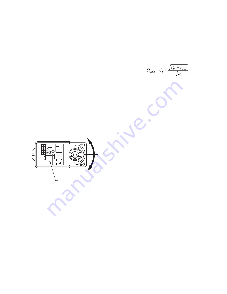
Manual Override

1.

Remove Actuator cover and DISCONNECT POWER 

before operating actuator manually.

NOTE: Failure to disconnect power may cause dam-

age to the actuator gears.

2.

Press the clutch.

3.

Rotate valve stem to manually operate valve. Clockwise 

to close, Counter-Clockwise to open. See Fig. 11.

Fig. 11. Manual Operation.

MAINTENANCE

1.

Continual blinking indicates that the Actuator torque out-

put limit has been exceeded. This may have been 

caused by debris in the valve internals. Disconnect 

power and manually operate the valve to clear the 

debris. Reconnect power. The Actuator will automatically 

recalibrate and reset. If the problem reoccurs, inspect 

the valve body internally for debris.

2.

If the system experiences large amounts of pipe scale 

due to poor water conditions, as sometimes found in 

older or retrofit pipe systems, provisions should be made 

to keep the system clean. Proper water treatment is also 

recommended by the use of a Separator.

3.

If a separator is not used for system cleaning and filtra-

tion, the valves should be checked annually.

Operation

The differential pressure regulator maintains constant pressure 

drop (P

IN

 - P

OUT

) across the valve seat through a wide range 

of head pressures. At a given shaft position, flow through the 

valve will constant as defined by the formula:

where 

ρ

 is the density of the glycol mix.

P

IN

 changes constantly in a multi-zone system as other valves 

open and close, changing system flow and head pressure 

according to the characteristics of the supply pump curve. 

Reaction of the mechanical pressure regulator is 

instantaneous, eliminating changes in room temperature due 

to changes in fluid flow, and reducing the need for the control 

system to constantly operate the control portion of the valve to 

correct for the non-load related temperature changes that 

occur in a system with standard control valves.

At full flow in a 2-position control application, a VRW2 behaves 

as a flow limiter.

The pressure regulator takes a minimum pressure to operate, 

and has a maximum differential regulation capability. The 

pressure drop across a VRW Valve is comparable to the 

pressure drop across a control valve plus a balancing valve in 

a conventional system design.

SETTINGS AND ADJUSTMENTS

At the full open position, VRW valves will maintain flow at the 

gallons per minute rate determined by the DIP Switch settings 

shown in Table 4. Under steady state operation, the control 

system will only require the valve to open enough to satisfy 

load conditions. During morning recovery from night setback, 

the controller will usually command the valve to 100%. 

Coil flow can be confirmed by reading pressures at the supply 

inlet and return outlet, and using the system design data to 

calculate flow.

Note that the pressure regulator in this valve guarantees that 

the flow through the valve will not be affected by upstream 

changes in pressure. Unlike conventional balancing valves, it 

is not necessary to reconfirm flow after adjusting other valves. 

Any overflow during morning recovery due to oversized 

pressure regulated valves will not affect other valves in the 

system, provided pumps are capable of required flow.

M31293

CLOSE

OPEN

CLUTCH PUSH BUTTON

1

ON

23

4

5

6

1

ON

23

1    2    3   4    5

88

Summary of Contents for VRW2

Page 1: ...When used in a system with variable speed pump drives 3 way valves and coil bypass lines are not required Systems that utilize the capabilities of properly installed and adjusted pressure independent control valves may qualify for LEED points FEATURES Multi sized bodies from 2 to 6 inch pipes with wafer flanged connections Combination ANSI ASME Class 150 300 pressure rating Controls hot or chilled...

Page 2: ...low Capacity See Table 1 Body Pressure Rating maximum 580 psig 40 bar at 248 F 120 C Controlled Medium Water or Glycol solutions up to 50 Not suitable for combustible gases oil or steam Fluid Temperature Range 4 to 248 F 20 to 120 C Minimum Differential Pressure See Table 1 Maximum Differential Pressure 58 psid 400 kPa Close off Pressure 101 psid 700 kPa maximum 0 2 leakage Flow Characteristics Eq...

Page 3: ...75 0 30 0 VRW2L 5 6 DN125 DN150 16 5 8 422 13 1 4 338 7 1 8 180 148 0 70 0 Table 3 Model Selection Valve Regulated Pipe fitting Body Pattern Valve Size Flow Rating Pressure Rating Valve Trim Actuator Secondary Spec Actuator Control Form Description VR Dynamic pressure regulated control valve W Combination size wafer flange 2 2 way J Valve size 2 1 2 and 3 in DN65 and DN80 K Valve size 3 and 4 in D...

Page 4: ...e a trained experienced licensed service technician 4 After installation is complete check out product opera tion as provided in these instructions Preparation CAUTION Equipment Damage Hazard Foreign particles like sand and metal chips can damage valve seals and regulator diaphragm For trouble free operation of the product good installation practice must include initial system flushing and chemica...

Page 5: ...ximum Flow Dip Switches so that the actuator limits the valve position to the maximum flow rate required Select the actuator dipswitch setting from Table 4 If adjusting the Dip Switch settings after power has been connected press the Reset Button to input the new setting ORIENTATION OF ACTUATOR ABOVE THE VALVE SPINDLE CORRECT M31296 DN 65 80 INCORRECT DN 65 80 85 85 M29519A M31286 1 ON 2 3 4 5 6 1...

Page 6: ...8 176 11 1 257 16 21 301 19 0 OFF ON ON ON OFF ON 2 7 84 8 5 4 113 7 1 125 7 9 179 11 3 263 16 59 310 19 6 ON OFF ON ON OFF ON 2 8 86 2 5 4 115 7 3 126 8 0 181 11 4 269 16 97 320 20 2 OFF OFF ON ON OFF ON 2 9 87 7 5 5 117 7 4 128 8 1 184 11 6 276 17 41 329 20 8 ON ON OFF ON OFF ON 3 0 89 1 5 6 119 7 5 130 8 2 187 11 8 282 17 79 339 21 4 OFF ON OFF ON OFF ON 3 1 90 0 5 7 121 7 6 131 8 3 189 11 9 28...

Page 7: ...6 8 148 9 3 146 9 2 221 13 9 363 22 90 445 28 1 ON ON OFF OFF ON OFF 5 4 108 6 8 149 9 4 146 9 2 221 13 9 364 22 96 448 28 3 OFF ON OFF OFF ON OFF 5 5 108 6 8 150 9 5 147 9 3 221 13 9 365 23 03 452 28 5 ON OFF OFF OFF ON OFF 5 6 109 6 9 151 9 5 147 9 3 221 13 9 366 23 09 455 28 7 OFF OFF OFF OFF ON OFF 5 7 110 6 9 153 9 7 147 9 3 221 13 9 367 23 15 458 28 9 ON ON ON ON OFF OFF 5 8 111 7 0 154 9 7 ...

Page 8: ...inks once 3 Release the Reset Button The indication LED should remain illu minated 4 Apply the new zero voltage to terminal 3 Any value between 0 7 Vdc 5 Press and release the Reset Button to memorize this value The LED should blink once as confirmation 6 Apply the new maximum voltage to terminal 3 Any voltage between 3 10 Vdc and at least 3 Vdc greater than the zero value 7 Press and release the ...

Page 9: ...ures At a given shaft position flow through the valve will constant as defined by the formula where ρ is the density of the glycol mix PIN changes constantly in a multi zone system as other valves open and close changing system flow and head pressure according to the characteristics of the supply pump curve Reaction of the mechanical pressure regulator is instantaneous eliminating changes in room ...

Page 10: ...Analog proportional control refers to direct acceptance of 2 10 Vdc or a 4 20 mA input signal Digital proportional control refers to direct acceptance of 24 Vac pulse width modulated input sig nal Floating control refers to direct acceptance of 24 Vac pulsed open and close commands from a tri state SP3T controller Two position control of non fail safe actuators shall be in the form of 24 Vac power...

Page 11: ...VRW2 DYNAMIC PRESSURE REGULATING FLANGED CONTROL VALVES 11 62 3116 01 ...

Page 12: ...Solutions Honeywell International Inc 1985 Douglas Drive North Golden Valley MN 55422 Honeywell Limited Honeywell Limitée 35 Dynamic Drive Toronto Ontario M1V 4Z9 customer honeywell com U S Registered Trademark 2010 Honeywell International Inc 62 3116 01 M S 02 10 Printed in U S A ...

Reviews: