background image

7

68-0049—2

VR8205; VR4205

␣ ␣ ␣ INSTALLATION

WIRING

Follow the wiring instructions furnished by the appli-

ance manufacturer, if available, or use the general instruc-
tions provided below. Where these instructions differ from
the appliance manufacturer, follow the appliance manufac-
turer instructions.

All wiring, including insulated quick connect terminals,

must comply with applicable electrical codes and ordi-
nances.

Disconnect power supply before making wiring connec-

tions to prevent electrical shock or equipment damage.

1. Check the power supply rating on the valve and make

sure it matches the available supply. Install transformer,
thermostat, and other controls as required.

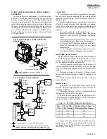
2. For VR4205, when the gas control is installed exter-

nal to the appliance, install the conduit cover on the conduit
fitting. Do not secure conduit cover at this time.

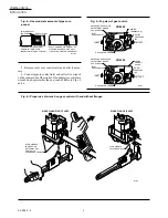
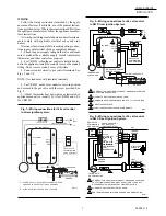
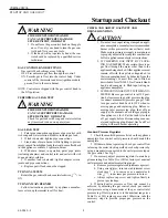
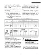
3. Connect control circuit to gas control terminals. See

Figs. 5 and 7-9.

NOTE: Use leadwires with insulated terminals.

4. For VR4205, make sure conduit cover is in position

and secured to the gas valve with the screw provided. See
Fig. 2.

5. Adjust thermostat heat anticipator as instructed in

appliance manual (i.e., usually 0.1A for VR4205 and 0.5A
for VR8205).

Fig. 7—Wiring connections for 120 volt control
in direct ignition system.

Fig. 8—Wiring connections for 24 volt control
in S87 Direct Ignition System.

IGNITION MODULE

L1
(HOT)

L2

LIMIT CONTROLLER

Q347 IGNITER-SENSOR

120V (GND)

VALVE

VALVE

GND

POWER SUPPLY.  PROVIDE DISCONNECT MEANS 
AND OVERLOAD PROTECTION AS REQUIRED.

ALTERNATE LIMIT CONTROLLER LOCATION.

M3090A

BURNER

120V 

VR4205
DUAL VALVE 
COMBINATION
GAS CONTROL

L2

L1

2

1

1

2

WHITE

BLUE

BLACK

BLUE

HOT 
SURFACE
IGNITER-
SENSOR

VALVE
VALVE (GND)

24V
TH-W
24V (GND)

GND (BURNER)

S89C,G,J/S890C,G,J 
HOT SURFACE 
IGNITION CONTROL

L2

HSI

L1

HSI

LIMIT
CONTROLLER

BURNER 
GROUND

THERMOSTAT
OR CONTROLLER

DUAL VALVE 
COMBINATION
GAS CONTROL

POWER SUPPLY. PROVIDE DISCONNECT MEANS AND OVERLOAD 
PROTECTION AS REQUIRED.  MAKE SURE L1 AND L2 ARE NOT 
REVERSED; THIS WOULD PREVENT FLAME DETECTION.

ALTERNATE LIMIT CONTROLLER LOCATION.

SEN TERMINAL AND Q354 FLAME SENSOR ON D MODELS ONLY.

M9047

MV

MV

L1

(HOT)

L2

VENT 
DAMPER PLUG

1

2

1

2

3

3

SEN

Q354 FLAME
SENSOR

Fig. 9—Wiring connections for 24 volt control
in S89C Direct Ignition System.

24V

24V (GND)

S87 CONTROL MODULE

ALARM

VALVE

VALVE

GND

TEMPERATURE 
CONTROLLER

POWER SUPPLY. PROVIDE DISCONNECT MEANS AND OVERLOAD 
PROTECTION AS REQUIRED.  

ALTERNATE LIMIT CONTROLLER LOCATION.

MAXIMUM IGNITER-SENSOR CABLE LENGTH:  3 ft. [.9 m] OR LESS.

3 A REPLACEABLE FUSE.

ALARM TERMINAL PROVIDED ON SOME MODELS.

M9043

MV

MV

L1

(HOT)

L2

1

2

1

2

3

DUAL VALVE
COMBINATION
GAS CONTROL

Q347 IGNITER-SENSOR

BURNER

4

4

5

IGNITER-SENSOR AND 
BURNER GROUND

3

5

ALARM, IF USED

Summary of Contents for VR8205

Page 1: ...tomatic valve opens on thermostat call for heat and closes when call for heat ends Diaphragm operatedsecondautomaticvalveopensunder control of the regulator and closes if gas or power supply is interrupted Two positiongascontrolknobhasONandOFFpositions All adjustments and wiring connections accessible from top of the control Compact size Straight through body pattern right angle adapters available...

Page 2: ...o provide ease of stocking ease of handling and maximum replacement value TRADELINE model specifications are the same as those of standard models except as noted below TRADELINE MODEL AVAILABLE VR8205A Dual Automatic Combination Gas Control for Direct Ignition Systems Models for natural or LP gas ADDITIONAL FEATURES 3 8 in bushing 3 4in straightflangeassembly withO ringandscrews Tool for flange he...

Page 3: ...m the upright position of the gas control knob including vertically TEMPERATURE RATING VR8205A C H VR4205H 0 F to 175 F 18 C to 79 C VR8205M P K VR4205M P 40 F to 175 F 40 C to 79 C DIMENSIONS See Fig 1 APPROVALS AmericanGasAssociationdesigncertificate L2025006 CanadianGasAssociationdesigncertificate L2025006 Australian Gas Association design certificate 4214 Approved for Delta C applications ACCE...

Page 4: ...r natural gas on an LP gas system or a gas control set for LP gas on a natural gas system 2 When making conversion main pilot burner orifices must be changed to meet appliance manufacturer specifications Refer to appliance manufacturer instructions for orifice specifications and changeover procedure Gas controls are factory set for natural and manufactured or LP gas Do not attempt to use a control...

Page 5: ...essive heat To assure proper operation follow these guidelines Locate gas control in a well ventilated area Mount gas control high enough above the cabinet bottom to avoid exposure to flooding or splashing water Assure the ambient temperature does not exceed the ambient temperature ratings for each component Cover gas control if appliance is cleaned with water steam or chemicals or to avoid dust a...

Page 6: ...ntrol inlet and outlet if neces sary 6 Connect pipe to control inlet and outlet Use wrench on the square ends of the control If an adapter is used place wrench on adapter rather than on control Refer to Figs 5 and 6 TWO IMPERFECT THREADS GAS CONTROL THREAD PIPE THE AMOUNT SHOWN IN TABLE 4 FOR INSERTION INTO GAS CONTROL APPLY A MODERATE AMOUNT OF PIPE COMPOUND TO PIPE ONLY LEAVE TWO END THREADS BAR...

Page 7: ...ition system Fig 8 Wiring connections for 24 volt control in S87 Direct Ignition System IGNITION MODULE L1 HOT L2 LIMIT CONTROLLER Q347 IGNITER SENSOR 120V GND VALVE VALVE GND POWER SUPPLY PROVIDE DISCONNECT MEANS AND OVERLOAD PROTECTION AS REQUIRED ALTERNATE LIMIT CONTROLLER LOCATION M3090A BURNER 120V VR4205 DUAL VALVE COMBINATION GAS CONTROL L2 L1 2 1 1 2 WHITE BLUE BLACK BLUE HOT SURFACE IGNIT...

Page 8: ...inburner is properly adjusted for complete combustion Follow appliance manufacturer instructions 2 IF CHECKING GAS INPUT BY CLOCK ING GAS METER Make certain there is no gas flow through the meter other than to the appliancebeingchecked Otherappliancesmust remain off with their pilots extinguished or their consumption must be deducted from the meter reading Convert flow rate to Btuh as describedinf...

Page 9: ...aracteristics TABLE 5A PRESSURE REGULATOR SPECIFICATION PRESSURES in wc Model Type Nominal Inlet Factory Set Nominal Outlet Pressure Setting Range Type of Gas Pressure Range Step Full Rate Step Full Rate Standard Natural 5 0 7 0 3 5 3 0 5 0 slow opening LP 12 0 14 0 10 0 8 0 12 0 Step opening Natural 5 0 7 0 0 9 3 5 3 0 5 0 LP 12 0 14 0 2 2 10 0 8 0 12 0 TABLE 5B PRESSURE REGULATOR SPECIFICATION P...

Page 10: ...tor is de energized closing the channel to the pressure regulator and opening a channel to the under side of the second automatic valve operator valve dia phragm The combination of spring pressure under the second automatic valve diaphragm and lack of outlet pres sure holds the diaphragm firmly closed Gas flow to the main burner is blocked by both valves Regular preventive maintenance is important...

Page 11: ...gmoregasflowto the gas control outlet This decreases gas pressure under the second automatic valve diaphragm and repositions the valve disc further from the seat Thus flow of gas through the second automatic valve is increased and outlet pressure rises to the desired level Fig 10 Position of gas control components during thermostat off cycle Slow Opening Regulation Slow opening gas controls functi...

Page 12: ...ressurecloses the second automatic valve to provide a second barrier to gas flow Fig 11 Position of gas control components during burner on cycle Service WARNING FIRE OR EXPLOSION HAZARD CAN CAUSE PROPERTY DAMAGE SEVERE INJURY OR DEATH Do not disassemble the gas control it contains no replaceable components Attempted disassembly or repair may damage the control CAUTION Do not apply a jumper across...

Page 13: ...e It must be replaced in case of any physical damage such as bent terminals missing or broken parts stripped threads or evidence of exposure to heat IMPORTANT Follow the operating instructions pro vided by the manufacturer of your heating appliance The information below will be of assistance in a typical control application but the specific controls used and the procedures outlined by the manufac ...

Reviews: