


2
control.
3. Install sediment trap in gas supply line. Refer to Fig. 1.
INSTALL CONTROL
1. This control can be mounted 0-90 degrees, in any
direction, from the upright position of the gas control knob,
including vertically.
2. Mount the control so gas flow is in direction of arrow
on bottom of control.
3. Thread pipe the amount shown in Table 3 for insertion
into control. DO NOT THREAD PIPE TOO FAR. Valve
distortion or malfunction may result if pipe is inserted too
deeply.
WARNING
FIRE OR EXPLOSION HAZARD
CAN CAUSE PROPERTY DAMAGE, SEVERE IN-
JURY, OR DEATH
Follow these warnings exactly:
1. Disconnect power supply before wiring to prevent
electrical shock or equipment damage.
2. To avoid dangerous accumulation of fuel gas, turn
off gas supply at appliance service valve before
starting installation and perform Gas Leak Test
following installation.
3. Do not bend pilot gas tubing at control or at pilot
burner after compression fitting is tightened. Gas
leakage at the connection may result.
4. Always install sediment trap in gas supply line to
prevent contamination of gas control.
5. Do not force gas control knob. Use only your hand
to turn gas control knob. If the knob will not operate
by hand, the control should be replaced by a
qualified service technician. Force or attempted
repair may result in fire or explosion.
CAUTION
Never apply a jumper across (or short) gas control
coil terminals. This may burn out thermostat heat
anticipator.
IMPORTANT
These gas controls are shipped with protective seals
over inlet and outlet tappings. Do not remove seals
until ready to connect piping.
Follow the appliance manufacturer’s instructions if avail-
able; otherwise, use the instructions provided below as a
guide.
CHOOSE LOCATION
Do not locate the combination gas control where it may
be affected by steam cleaning, high humidity, dripping
water, corrosive chemicals, dust or grease accumulation,
or excessive heat. To ensure proper operation, follow these
guidelines.
•
Locate in a well ventilated area.
•
Mount high enough above the cabinet bottom to
avoid exposure to flooding or splashing water.
•
Ensure the ambient temperature does not exceed the
ambient temperature ratings for each component.
•
Cover gas control if appliance is cleaned with water,
steam, or chemicals or to avoid dust and grease
accumulation.
•
Avoid locating where exposure to corrosive chemical
fumes or dripping water are likely.
Mount combination gas control in the appliance vesti-
bule on the gas manifold. In replacement applications,
mount gas control in the same location as the old control.
INSTALL PIPING TO CONTROL
All piping must comply with local codes and ordinances
or with National Fuel Gas Code (ANSI Z223.1 NFPA No.
54), whichever applies. Tubing installation must comply
with approved standards and practices.
1. Use new, properly reamed pipe free from chips. If
tubing is used, make sure ends are square, deburred, and
clean. All tubing bends must be smooth and without defor-
mation.
2. Run pipe or tubing to the control. If tubing is used,
obtain a tube-to-pipe coupling to connect tubing to the
TABLE 3—NPT PIPE THREAD LENGTH (IN.).
OVERALL
MAXIMUM DEPTH PIPE
PIPE
THREAD
CAN BE INSERTED
SIZE
LENGTH
INTO CONTROL
3/8
9/16
3/8
1/2
3/4
1/2
3/4
13/16
3/4
1
9/16
1
4. Apply moderate amount of good quality pipe com-
pound to adapter, leaving two end threads bare. Refer to
Fig. 2. (On LP gas installations, use compound resistant to
LP gas.) Do not use Teflon tape.
5. Remove seals over control inlet and outlet, if neces-
sary.
6. Connect pipe to control inlet and outlet. To tighten inlet
and outlet connections, use wrench on projecting wrench
boss. Refer to Figs. 3 and 4.
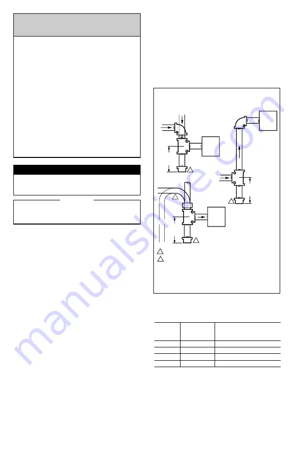
Fig. 1—Install sediment trap.
GAS
CONTROL
GAS
CONTROL
HORIZONTAL
DROP
PIPED
GAS
SUPPLY
PIPED
GAS
SUPPLY
3 IN.
(76 MM)
MINIMUM
3 IN.
(76 MM)
MINIMUM
RISER
GAS
CONTROL
TUBING
GAS
SUPPLY
HORIZONTAL
DROP
3 IN.
(76 MM)
MINIMUM
RISER
M3077
2
1
2
2
1
2
ALL BENDS IN METALLIC TUBING SHOULD BE SMOOTH.
CAUTION: SHUT OFF THE MAIN GAS SUPPLY BEFORE REMOVING
END CAP TO PREVENT GAS FROM FILLING THE WORK AREA. TEST
FOR GAS LEAKAGE WHEN INSTALLATION IS COMPLETE.