background image

8

7

BATTERY INSTALLATION

MAIN UNIT

1. Open the battery compartment door.

2. Install 2 batteries (UM-3 or “AA” size 1.5V) matching 

the polarity as shown in the battery compartment.

3. Replace the battery compartment door.

4. Connect the 6V AC/DC adapter to activate

the Color LCD display.

NOTE: AC/DC adapter should be connected at all times,

even during the battery replacements, otherwise barometric

pressure history will be lost.


LOW BATTERY WARNING

A low-battery indicator [        ] will appear on the indoor or

remote temperature reading line of the main unit warning that

the corresponding batteries have to be replaced.

3. Position the remote sensor so that is faces the main unit

(receiver), minimizing obstructions such as doors, walls,

and furniture.

4. Though the remote sensors are weather-resistant, they

should be placed away from direct sunlight, rain or snow.

BATTERY INSTALLATION

REMOTE SENSOR

NOTE: Install the batteries; select the channel and type of

temperature (ºC/ºF) before you mount the sensor.

1. Remove the screws from the battery compartment with a

small Phillips screwdriver.

2. Set the channel. The switch is located in the battery

compartment.  Channel 1 is typically selected if

only 1 remote sensor is being used.

3. If you are using more than one sensor, select a different

channel for each sensor.

4. Install two “AA” size alkaline batteries (not included)

matching to the polarities shown in the battery compartment.

5. Replace the battery compartment door and secure the screws.

6. Secure the remote sensor in the desired location.

HOW TO USE THE TABLE STAND

The main unit has a removable transparent table stand,

which supports the unit on the flat surface. The remote sensor

can be mounted on the wall, using wall-mount recessed hole

or placed on a flat surface.

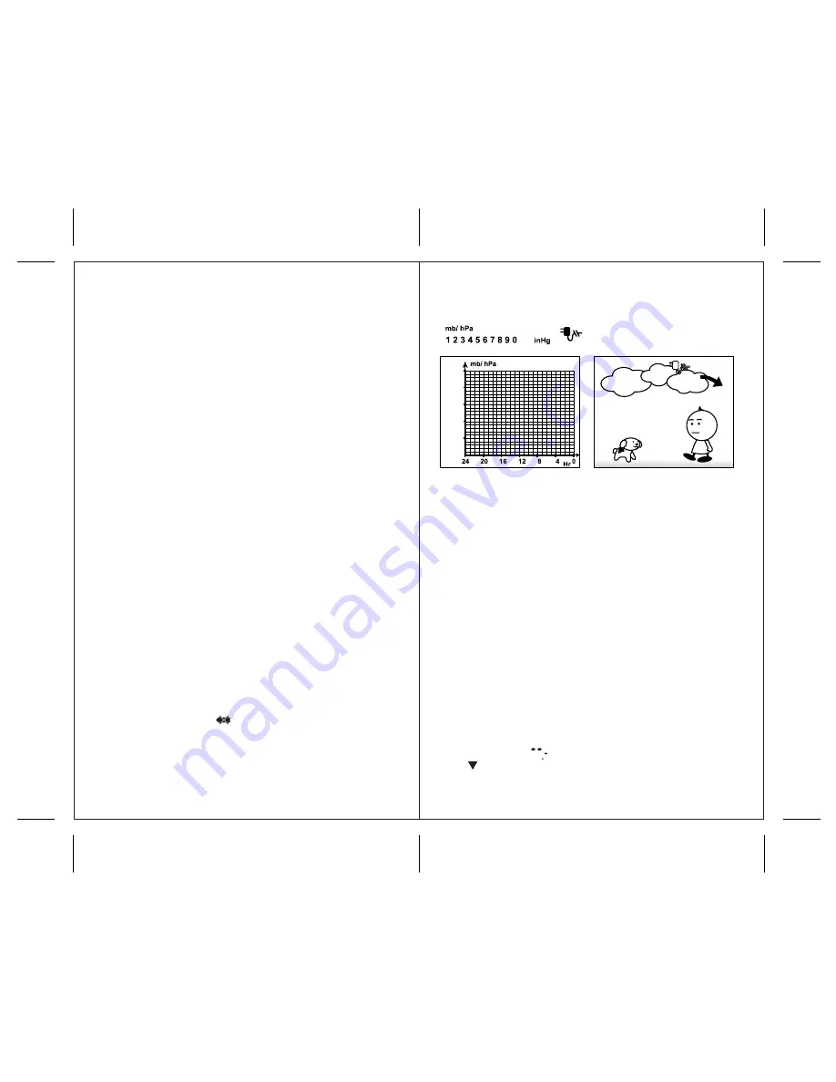
After the AC/DC adapter is connected to the main unit, the

color LCD will be activated. It will toggle with 10 seconds

delay between barometric pressure history chart and

cartoon-animated weather forecast.

The main unit can be programmed to display just one of

the above.

GETTING STARTED

After batteries are installed, remote sensor(s) will transmit a

temperature readings at 45 second intervals. The main unit

may take up to 2 minutes to receive the initial readings.

Upon successful reception, remote temperature will be

displayed. The main unit will automatically update readings

at 45-second intervals.
If no signals are received from the remote sensor (s) within

2 minutes, dashes “      ” will be displayed. Press and

hold [      ] button on the main unit for 2 seconds to initiate

another signal search.

Once AC/DC adapter is connected, the Color display will

toggle (TOGGLE mode) between the following modes:

Summary of Contents for TE601CELW

Page 1: ...1 1 Color Weather Forecaster with Indoor Outdoor Thermometer USER MANUAL TE601CELW ...

Page 2: ...ould know PRODUCT OVERVIEW MAIN UNIT FEATURES Wireless sensor transmits temperature to the main unit from up to 100 feet away Multi channel capability to monitor temperature in up to 3 remote locations Indoor and Remote temperature displays Barometric pressure condition displayed in 3 trend indicators Rising Steady and Falling Color animated weather forecast in 5 large graphic icons Sunny Partly C...

Page 3: ...HER FORECAST or BAROMETRIC PRESSURE CHART display mode b Selects the SINGLE or DEFAULT TOGGLE display modes c Increases altitude in ALTITUDE ADJUSTMENT mode E UNIT BUTTON a Selects pressure display in mB hPa inHg or mmHg b Selects altitude adjustment display in feet or meters c Decreases altitude in ALTITUDE ADJUSTMENT mode G MODE BUTTON Changes display modes and confirms settings H UP BUTTON Incr...

Page 4: ...T after each battery change using paper clip or similar tool 6 During an initial setup place the main unit as close as possible to the remote sensor 7 After reception is established remote temperature will appear on the receiver s display position the remote sensor and main unit within the effective transmission range of 100 feet NOTE 1 Avoid setting the time and date on the main unit before the o...

Page 5: ...are using more than one sensor select a different channel for each sensor 4 Install two AA size alkaline batteries not included matching to the polarities shown in the battery compartment 5 Replace the battery compartment door and secure the screws 6 Secure the remote sensor in the desired location HOW TO USE THE TABLE STAND The main unit has a removable transparent table stand which supports the ...

Page 6: ...al depends on the positioning and location of the clock Always place the main unit by the window for better reception Within concrete wall rooms such as basements or office buildings the received signal may be weakened Always place the unit near the window WWVB RADIO CONTROLLED TIME The NIST National Institute of Standards and Technology radio station is located in Ft Collins Colorado It transmits...

Page 7: ...arometric pressure history chart with 10 seconds delay After AC adapter is connected the TOGGLE mode will be activated automatically SINGLE DISPLAY MODE Shows only when selected by the user by pressing TOGGLE button 1 Weather forecast with animated cartoon images 2 Barometric pressure history in chart format for the past 24 hours with pressure in numerals WEATHER FORECAST The Weather Forecaster is...

Page 8: ...ode LOST COMMUNICATION If the main unit display for the remote sensor goes blank press and hold button for 2 seconds to begin a new signal search If the signal still isn t received please make sure that 1 The remote sensor is in the proper location 2 The distance between the main and remote units is not over 100 feet 3 The path between units is clear of obstacles Shorten the distance between units...

Page 9: ...ing or 6 Press ALARM again to exit 7 Repeat the same procedure to set any of alarms weekly daily or pre alarm SNOOZE When the alarm sounds press the SNOOZE LIGHT button to temporarily stop the alarm If not disabled the alarm sound will resume after 5 minutes If the alarm is not disabled after that it will sound for 4 more minutes and then will stop by itself DISABLING ALARM Press ALARM button on t...

Page 10: ...his device may not cause harmful interference and 2 This device must accept any interference received including interference that may cause undesired operation Warning Changes or modification to this unit not expressly approved by the party responsible for compliance could void the user s authority to operate the equipment NOTE This equipment had been tested and found to comply with the limits for...

Page 11: ...s not cover damages or wear resulting from accident misuse abuse commercial use or unauthorized adjustment and repair Note that online product registration is required to ensure valid warranty protection To register your product go to our Company website at www hidekielectronics us Click Online Product Registration under the Customer Service menu Should you require assistance with this product and...

Reviews: