Honeywell T8424D Installation Instructions Manual Download Page 2

T8424D ELECTRONIC MULTISTAGE THERMOSTAT

69-1386-1

2

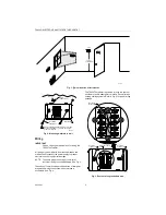
Fig. 1. Typical location of thermostat.

Fig. 2. Mounting wallplate to wall.

Wiring

IMPORTANT

Use an 18-gauge maximum wire for wiring the 
T8424 Thermostat.

All wiring must comply with local electrical codes and 

ordinances. Disconnect the power supply to prevent 
electrical shock or equipment damage.

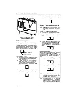
NOTE: To ensure proper mounting of thermostat, 

restrict all wiring to the shaded area. See Fig. 3.

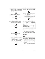
The shape of the terminals permits insertion of straight or 
wraparound wiring connections; either method is 

acceptable. See Fig. 4.

The T8424 Thermostat is powered through the system 
transformer and is adaptable to most 24 Vac multistage 

heating-cooling systems. Refer to Fig. 5 for typical wiring 
hookups.

Fig. 3. Restrict wiring to shaded area.

5 FEET

[1.5 METERS]

YES

NO

NO

NO

M11338

M12202A

WALL

WALL  
ANCHORS (2)

WALLPLATE

WHEN USING WALL ANCHORS, DRILL 3/16 INCH 
HOLES FOR DRYWALL, 7/32 INCH HOLES FOR
PLASTER OR WOOD.

MOUNTING 
SCREWS (2)

1

1

KEEP WIRING IN
SHADED AREA

MOUNTING 
SCREW HOLE

MOUNTING 
SCREW HOLE

WIRING ENTRANCE
HOLE

M20211

G

C

R

Y

W1

Y2

W2

B

O

Summary of Contents for T8424D

Page 1: ...le for your application 3 Installer must be a trained experienced service technician 4 After installation is complete check out product operation as provided in these instructions CAUTION Electrical Shock or Equipment Damage Hazard Can shock individuals or short equipment circuitry Disconnect power supply before installation Location Install the thermostat about 5 ft 1 5m above the floor in an are...

Page 2: ... shape of the terminals permits insertion of straight or wraparound wiring connections either method is acceptable See Fig 4 The T8424 Thermostat is powered through the system transformer and is adaptable to most 24 Vac multistage heating cooling systems Refer to Fig 5 for typical wiring hookups Fig 3 Restrict wiring to shaded area 5 FEET 1 5 METERS YES NO NO NO M11338 M12202A WALL WALL ANCHORS 2 ...

Page 3: ...e heating equipment turns on on most systems When using an electric heat thermostat the fan starts and stops with the heating equipment Slide the FAN switch in the bottom left corner of the thermostat to select the desired fan setting SYSTEM Switch System switch settings control thermostat operation as follows Cool The thermostat controls the cooling system Off Both heating and cooling are off Hea...

Page 4: ... set the F C indication and heat cycle rate 1 If the temperature is displayed in F set the tem perature setpoint to 52 F If the room temperature is displayed in C set the temperature setpoint to 11 C 2 Press the keys simultaneously for more than one second to light all segments on display and to enter installer setup mode When the keys are released a two digit software revision code is dis played ...

Page 5: ...thm C3 Aggressive algorithm can cause overshooting 13 Press the key again Current configuration CC is displayed A typical example is shown but CC varies by model This information is for factory use only Table 1 Heating Cycle Rates for Stage Two Heating a High efficiency furnace bRefer to equipment manufacturer s instructions 14 Press the key to save all changes exit installer setup mode and return...

Page 6: ... Press the key to lower the temperature setting several degrees below the room temperature After approximately five minutes the cooling equipment should start The fan starts and stops with the cool ing equipment 3 Press the key to raise the temperature setting above the room temperature Cooling system should shut down NOTE To bypass the 5 minute delay see the Optional System Checkout section Fan 1...

Reviews: