background image

T775A/B/M SERIES 2000 ELECTRONIC STAND-ALONE CONTROLLERS

19

62-0254—13

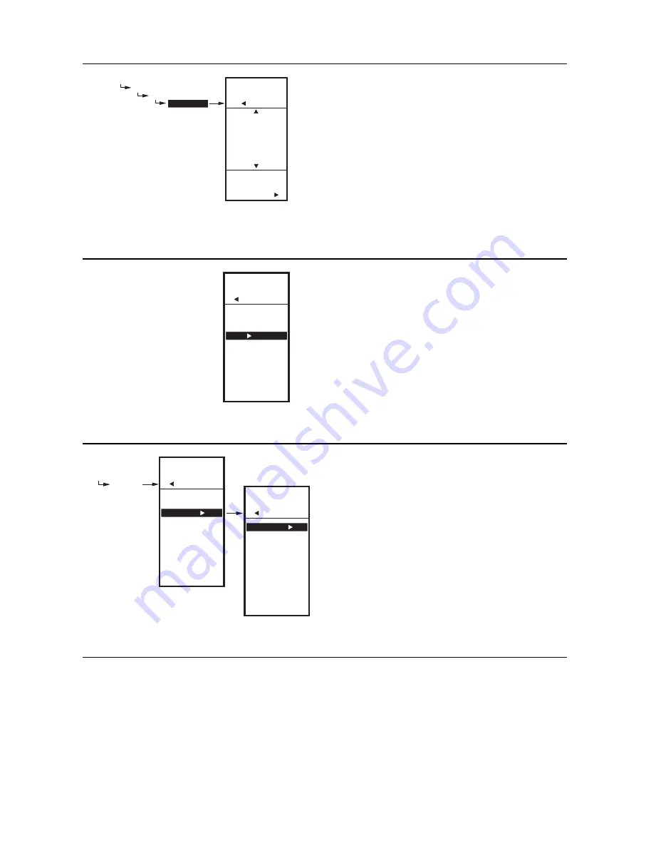
Fig. 41. Setup - Sensors - Sensor A - Label.

2.2.2.3. LABEL 

(the sensor input)

For a sensor already labeled, the display positions to and 

highlights that label.

1.

From the Sensor A selections, use the


and


buttons to highlight LABEL.

2.

Press the 


button to display the label list.

3.

Use the


and


buttons to scroll through list 

and highlight the desired label.

You may need to scroll up or down to view all 

possible labels.

4.

Use the 


button to accept the highlighted label 

and exit the list.

NOTE: The label names in list order are: Sensor, 

Boiler, Outdoor, Duct, Dischrg, Chiller, Room, 

Supply, Return, and Animals.

Fig. 42. Setup - Sensors - Sensor A - Exit.

2.2.2.4. Exit Sensor A Setup

Press the

button to exit Sensor A selections and return 

to the Sensors menu.

or

Use the


and


buttons to highlight EXIT and press 

the 


button.

Fig. 43. Setup - Sensors - Sensor B Menu.

2.2.3. SENSOR B

For the T775M2030 and T775M2048 models only, which 

have a High/Low modulating temperature limit, the LIMIT 

item displays on the Sensor B menu.

1.

From the Sensors menu, use the


button to 

highlight SENSOR B.

2.

Press the  


button to display the Sensor B menu.

2.2.3.1. CALIBRATE

Setting the calibration value is accomplished the same 

way as the Sensor A. See “2.2.2.2. CALIBRATE (the 

sensor)” on page 18.

2.2.3.2. LABEL

Setting the label is accomplished the same way as the 

Sensor A. See “2.2.2.3. LABEL (the sensor input)” on 

page 19.

SETUP

SENSORS
 SENSOR 


A

  LABEL

SETUP

SENSORS

SENSOR  A

LABEL

SELECT

LABEL FOR

SENSOR  A

SENSOR  A

BOILER A

OUTDOOR A

DUCT A

DISCHRG A

CHILLER A

ROOM A

M24505

SETUP

SENSORS

SENSOR A

UNITS

CALIBRATE

LABEL

EXIT

M24506

SETUP

SENSORS

SETUP

SENSORS

# SENSORS

SENSOR A

SENSOR B

EXIT

SETUP

SENSORS

SENSOR B

CALIBRATE

LABEL

LIMIT

EXIT

M24507

All manuals and user guides at all-guides.com

Summary of Contents for T775A

Page 1: ...elay Outputs Analog Mod Outputsb b The modulating analog outputs are 4 20 mA 0 10 Vdc 2 10 Vdc or Series 90 selectable Floating Outputsc c Each floating output eliminates two SPDT relays Sensor Inputs Nbr of Sensors Included Enclosure T775A2009 Standard T775A1001 1 None None 1 1 NEMA 1 T775B2016 Standard N A 2 None 1 2 1 NEMA 4X T775B2024 Standard T775C1009 T775D1008 4 None 2 2 1 NEMA 4X T775B2032...

Page 2: ...insertion 107408 Heat Conductive Compound 4 ounce 50001774 001 Immersion Well stainless steel 304 1 2 in threading Product Changes Below are the changes to T775A B M models starting with Series 3 March 2009 Series 3 can be identified by the sideways 3 after the part number on the device label 1 Modulating high and low limit now both function in either the heat or the cool mode 2 MIN ON added 3 SYN...

Page 3: ... on the back of the enclosure using 6 or 8 screws screws are not provided and must be obtained separately Use controller dimensions in Fig 1 on page 2 as a guide The controller may be mounted in any orientation However mounting in the orientation shown in Fig 1 on page 2 permits proper viewing of the LCD display and use of the keypad NEMA 4 Enclosure Mounting For models with NEMA 4 enclosures ensu...

Page 4: ...le NOTE Each T775 controller must be wired to its own sensor s However a benefit of the T775 controller s accuracy is that there is no more than a 2 F 7 C differential between any two T775 controllers Multiple Parallel Sensors Multiple sensors can be parallel series wired to sense average temperatures in large spaces To maintain control accuracy the number of sensors to be parallel series wired mu...

Page 5: ...or sensor and low voltage wiring Knockouts C D and E can be used to gain access to the load relay output terminals and 120 240 Vac power wiring Controller Wiring Method Wire the sensors and outputs then wire the power connection Each terminal can accommodate the following gauges of wire Single wire from 14 AWG to 22 AWG solid or stranded Multiple wires up to two 22 AWG stranded For 24 120 or 240 V...

Page 6: ...or mA W R B Series 90 a Modulating Output Mod 2 M24474 C NO NC C NO NC C NC NO C NC NO T T T T B R W B R W SENSOR A SENSOR B MOD 2 MOD 1 KNOCKOUT A DIGITAL INPUT POWER 120 240 VAC OUTPUT RELAY 2 KNOCKOUT D POWER 24 VAC OUTPUT RELAY 1 KNOCKOUT C KNOCKOUT E SENSORS A AND B USE THE TWO TT CONNECTIONS AND ARE POLARITY INSENSITIVE FOR MOD 1 AND MOD 2 CURRENT mA OR VOLTAGE VDC OUTPUT USE SIGNAL COMMON F...

Page 7: ... and 120 Vac Load Shown L1 HOT L2 24 VAC M24476A SENSOR A C NO NC C NO NC C NC NO C NC NO T T COM LOAD 4 NO LOAD 3 LOAD 2 LOAD 1 C COM NO COM NO COM NO SENSOR A C NO NC C NO NC T T COM LOAD 2 LOAD 1 NO COM NO COM 120V M33846 C 120 COM 240 POWER SUPPLY L1 HOT L2 SENSOR A C NO NC C NO NC T T COM LOAD 2 LOAD 1 NO COM NO COM 240V M33847 C 120 COM 240 POWER SUPPLY L1 HOT L2 SENSOR A C NO NC C NO NC C N...

Page 8: ... C NO NC M31361 CLOSE RELAY TO DRIVE DEVICE CLOSED RELAY 1 SHOWN RELAYS 1 AND 3 ARE USED FOR CLOSE CLOSE RELAY TO DRIVE DEVICE OPEN RELAY 2 SHOWN RELAYS 2 AND 4 ARE USED FOR OPEN THE RELAYS MUST BE WIRED IN PAIRS WITH RELAYS 1 AND 2 BEING THE FIRST PAIR AND RELAYS 3 AND 4 BEING THE SECOND PAIR 1 2 1 2 120 240 VAC LINE CLOSE DEVICE COM OPEN NO COM NO COM RELAY 1 RELAY 2 M27228A MODULATING OUTPUT TE...

Page 9: ...R MINIMUM DRIVE CLOSED SIGNAL LESS THAN 0 17 VDC MAXIMUM DRIVE OPEN SIGNAL IS GREATER THAN 1 7 VDC USE SEPARATE TRANSFORMER FOR T775R WHEN USING 24 VAC INSERT 340 OHM RESISTOR INCLUDED ACROSS TERMINALS R AND W 1 2 3 MODULATING OUTPUT TERMINAL MOD 1 B R W B R W T1 T2 B W R POWER HONEYWELL ELECTRONIC SERIES 90 MODUTROL MOTOR 1 2 3 M24485A USE SEPARATE TRANSFORMER FOR T775R WHEN USING 24 VAC A 250 OH...

Page 10: ...S USED ALL MOTORS MUST BE IN PHASE CONNECT THE SAME TRANSFORMER LEAD TO T1 ON EACH MOTOR CONNECT THE OTHER TRANSFORMER LEAD TO T2 ON EACH MOTOR USE TEMPERATURE CONTROLLER SUCH AS H205 OR H705 OR T675A FOR CHANGEOVER CONTROL AUTHORITY OF MINIMUM POSITION POTENTIOMETER IF USED INCREASES WITH THE NUMBER OF MOTORS IN PARALLEL WITH ONE MOTOR 50 STROKE WITH TWO MOTORS 100 STROKE WITH THREE MOTORS 100 ST...

Page 11: ...xceeds the controller s calibration limits of 10 F 6 C you must use a heavier gauge wire For example with a wire run of 1 000 feet you must use 20 AWG wire or heavier in order to calibrate for wire loss within the limits of the controller See 2 2 2 2 CALIBRATE the sensor on page 18 for the instructions to enter the calibration value Fig 23 shows how sensor resistance varies with temperature for a ...

Page 12: ...ns and Use these buttons to move backward and forward through the Program and Setup menus Up and Down Arrow Buttons and Use these buttons to move your selection up and down through a menu or list When the desired item is highlighted you press the arrow button to display that item s content When a value is displayed e g 70 F the up and down arrows increase and decrease the value NOTE Once you selec...

Page 13: ... Using the Menus When you are working with the menus use the Left arrow button to scroll backward through the menus Right arrow button to select the highlighted menu item and display its content Up and Down arrow buttons and to scroll up and down through a list of items or to increase or decrease the value of a displayed parameter NOTE If you press the HOME button or there is no keypad activity fo...

Page 14: ...g mode the differential is above the setpoint The relay de energizes when the temperature falls to the setpoint As the temperature rises to the setpoint plus the differential the relay energizes Setpoint High Limit You can set a single irreversible setpoint high limit maximum value which is applied to all outputs Adjust the setpoint at any output to the desired maximum setpoint Then simultaneously...

Page 15: ... RNG or DIFFERNTL 2 Press the button to display the throttling range value 3 Use the and buttons to increase decrease the desired value Default 20 F 7 C Range 1 to 300 F 1 to 149 C 4 Press the button to accept the value and display the next option In heating mode the Differential is below the setpoint The relay de energizes when the temperature rises to the setpoint As the temperature drops to the...

Page 16: ...etback mode for this output For example if your setpoint is 70 F 21 C and you want the temperature to drop 10 F during setback mode enter 60 F 16 C as the setpoint for this output 1 From the menu use the and buttons to highlight SETBACK 2 Use the and buttons to increase decrease the desired setpoint temperature Default 60 F 16 C Range 40 to 248 F 40 to 120 C 3 Press the button to accept the value ...

Page 17: ...hose relays that are defined in Setup see 2 3 2 NBR OF RELAYS on page 24 For example if you configure only two relays then only two relays display on the appropriate menus Once in Setup mode you use the Left arrow button to scroll backward through the Setup menus Right arrow button to select the highlighted menu item and display its content Up and Down arrow buttons and to scroll up and down throu...

Page 18: ...the button to display the temperature units 3 Use the and buttons to highlight F or C Default F Fahrenheit 4 Press the button to accept the units and return to the Sensor A selections Fig 40 Setup Sensors Sensor A Calibrate 2 2 2 2 CALIBRATE the sensor Ensure that the wire size calibration value is within the limits See Temperature Sensor Calibration on page 11 1 From the Sensor A selections use t...

Page 19: ...or Use the and buttons to highlight EXIT and press the button Fig 43 Setup Sensors Sensor B Menu 2 2 3 SENSOR B For the T775M2030 and T775M2048 models only which have a High Low modulating temperature limit the LIMIT item displays on the Sensor B menu 1 From the Sensors menu use the button to highlight SENSOR B 2 Press the button to display the Sensor B menu 2 2 3 1 CALIBRATE Setting the calibrati...

Page 20: ... Sensor B can be assigned a high low limit so that as you are controlling temperature at Sensor A the control adjusts its modulating output to prevent exceeding the user entered limit for Sensor B 1 From the Sensor B menu use the button to highlight HI LIMIT or LOW LIMIT 2 Press the button display the LIMIT value 3 Use the and buttons to increase decrease the desired Limit value 4 Press the button...

Page 21: ...play only those relays that are defined in Setup see 2 3 2 NBR OF RELAYS on page 24 For example if you configure only two relays then only two relays display on the appropriate menus The following procedures set up each modulating output and relay output Fig 48 Setup Outputs Modulating Output Menu 2 3 1 Setting up the Modulating Outputs 1 From the Output menu use the and but tons to highlight the ...

Page 22: ...e seconds and return to the Mod menu NOTES 1 The Integral time is factory set for 400 seconds This is a good middle range and should satisfy many applications The integral time can be increased for applications where sensed response is slow and can be decreased for applications where sensed response is fast e g discharge air control 2 As a starting point an optimal integral time for discharge air ...

Page 23: ...e and buttons to highlight SCHEDULE 2 Use the and buttons to highlight YES or NO Default YES 3 Press the button to accept the selection and return to the Mod menu Each output can be set up to follow or ignore the built in scheduler To disable the scheduler for all outputs see 2 3 3 1 USE SCHED on page 25 Fig 54 Setup Outputs Mod 1 2 Hide 2 3 1 6 HIDE The Hide option is used to prevent the MOD 1 an...

Page 24: ... 4 Press the button to accept the value and display the Outputs menu NOTES 1 The T775A B M models have the following outputs available T775A20191 relay output T775B2016up to 2 relay outputs T775B2024up to 4 relay outputs T775B2032up to 2 relay outputs T775B2040up to 4 relay outputs T775M2006no relay outputs T775M2014up to 4 relay outputs 2 The number of relay outputs entered here determines how ma...

Page 25: ...ON This is the minimum number of seconds of off time or on time for all relays 1 Press the button to display the Min Off On value 2 Use the and buttons to increase decrease the desired number of seconds from 0 to 990 sec onds in 10 second increments Default 0 zero Range 0 to 990 seconds 3 Press the button to accept the seconds and display the DI OPTIONS NOTES 1 The minimum OFF or ON time applies t...

Page 26: ...r NO Default YES 3 Press the button to accept the value and return to the Options menu Selecting YES shows the RT run time hours for each relay on the home screen displays NOTE Run times can be reset to zero for each individual relay You must do this for each relay that you want to reset to zero See 2 3 4 3 RESET RT run time hours on page 29 Fig 62 Setup Outputs Options Sync 2 3 3 5 SYNC synchroni...

Page 27: ... standard or floating The Floating option is only available on the T775B2016 T775B2024 T775B2032 and T775B2040 models For these models this selection displays only for Relay 1 and or Relay 3 1 Press the button to display the Type values 2 Use the and buttons to select STANDARD OR FLOATING Default STANDARD not floating 3 Press the button to accept the value and return to the Relay menu If you selec...

Page 28: ... run time is defined as the time needed to move the actuator from the fully closed to fully open position and visa versa Fig 68 Setup Outputs Floating Relay Integral 2 3 4 1 1 2 INTEGRAL modulating floating relay only The Actuator option displays only on the T775B2016 T775B2024 T775B2032 and T775B2040 models when the Type option Floating 1 From the menu use the and buttons to highlight INTEGRAL 2 ...

Page 29: ...return to the Relay menu An individual output can be selected to be controlled or not controlled by the schedule If NO is selected the Setback selection does not appear in the Program menu for this output Fig 71 Setup Outputs Relay Reset Runtime 2 3 4 3 RESET RT run time hours This selection displays only if Show RT YES is selected during Output Options setup see 2 3 3 4 SHOW RT show run time hour...

Page 30: ...scheduling instructions You may want to use this procedure simply as a reference to locate the particular option or parameter of interest NOTES 1 If you press the HOME button or there is no keypad activity for four minutes you exit Scheduling mode and return to the home screen 2 If you press the MENU button you exit Scheduling mode and return to the menu To create or change a schedule you use the ...

Page 31: ... return to the Options menu Fig 76 Schedule Options System Date 3 2 2 SET DATE Setting the system date is required to enable the controller to follow daylight saving time IMPORTANT To properly account for Daylight Saving time be sure to set the Date before setting the Time 1 From the Options menu use the and but tons to highlight SET DATE 2 Press the button to display the current system date setti...

Page 32: ... selected time period For each selected time period the schedule event E1 and E2 parameters are exactly the same as shown in Fig 78 SCHEDULING EXAMPLE Setting the schedule is independent of the temperature settings for the relay outputs The following illustrates a weekly schedule for daytime setpoint and night time setback use and shows the factory default settings To set a schedule continue with ...

Page 33: ...menu 3 3 3 E2 SETPOINT setpoint for event 2 Creating the setpoint for event 2 is accomplished the same way as the first event See 3 3 1 E1 SETPT setpoint for event 1 on page 33 3 3 4 E2 TIME time for event 2 Creating the time for event 2 is accomplished the same way as the first event See 3 3 2 E1 TIME time for event 1 above 3 3 5 EXIT exit from selected time period settings After entering the tim...

Page 34: ...tatus as described below Error Message There is a two character error code that displays in response to controller software problems EE EEPROM Failure The values read back from the EEPROM are not the same as written into the EEPROM This error cannot be field repaired Replace the device Diagnostic Messages There are two diagnostic messages that can display in response to sensor problems The diagnos...

Page 35: ... of the FCC rules These limits are designed to provide reasonable protection against harmful interference in residential installations This equipment generates uses and can radiate radio frequency energy and if not installed and used in accordance with the instructions may cause harmful interference to radio communications However there is no guarantee that interference will not occur in a particu...

Page 36: ...2 Printed in United States By using this Honeywell literature you agree that Honeywell will have no liability for any damages arising out of your use or modification to the literature You will defend and indemnify Honeywell its affiliates and subsidiaries from and against any liability cost or damages including attorneys fees arising out of or resulting from any modification to the literature by y...

Reviews: