Honeywell SMX-AUS User Manual Download Page 28

User’s Guide SMX-AUS 


28 

NS-MN-0032 / 11.2020


7.2.3


ENABLE OR DISABLE – LOGIC ZONE 


Perform the following steps to enable or disable Logic Zones:  

1.


In

 ENABLE/DISABLE

 tab, tap 

LOGIC ZONES

 to enable or disable a logic zone. 

 
The 

Logic Zones 

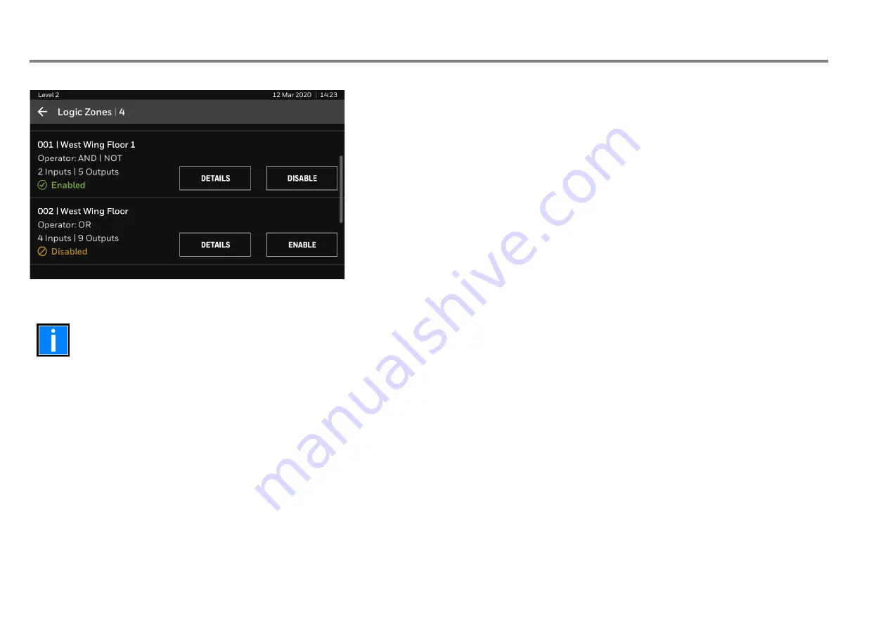
screen opens with a list of programmed logic zones in the panel. 


2.


Tap 

DETAILS

 to view operators applied, inputs and outputs associated with the logic zone. 

3.


Tap 

ENABLE

 to enable a logic zone or tap 

DISABLE

 to disable a logic zone. 

Fig. 26: Logic Zone Enable or Disable 


When a logic zone is disabled, all its associated outputs get inhibited from activation.  


In case, the output(s) are already activated by the logic zone, performing the logic zone disablement will deactivate all its associated output(s).  


A logic zone which is disabled, is evaluated as logic 0, if it is part of/ cascaded as an input to other logic zones.  


After the logic zone is re-enabled, all its associated output(s) return to the required state, as per the configured logic rule.  


Summary of Contents for SMX-AUS

Page 1: ...SMX AUS Fire Alarm Control Panel FACP User s Guide NS MN 0032 11 2020 ...

Page 2: ...f Honeywell International Inc While this information is presented in good faith and believed to be accurate Honeywell disclaims the implied warranties of merchantability and fitness for a purpose and makes no express warranties except as may be stated in its written agreement with and for its customer In no event is Honeywell liable to anyone for any direct special or consequential damages The inf...

Page 3: ... detector for example may not sense a first floor or basement fire Particles of combustion or smoke from a developing fire may not reach the sensing chambers of smoke detectors because Barriers such as closed or partially closed doors walls chimneys even wet or humid areas may inhibit particle or smoke flow Smoke particles may become cold stratify and not reach the ceiling or upper walls where det...

Page 4: ...It is the property owner s responsibility to conduct fire drills and other training exercises to make people aware of fire alarm signals and instruct them on the proper reaction to alarm signals In rare instances the sounding of a warning device can cause temporary or permanent hearing loss A life safety system will not operate without any electrical power If AC power fails the system will operate...

Page 5: ...adequate for all initiating and indicating device loops Most devices cannot tolerate more than a 10 I R drop from the specified device voltage Like all solid state electronic devices this system may operate erratically or can be damaged when subjected to lightning induced transients Although no system is completely immune from lightning transients and interferences proper grounding will reduce sus...

Page 6: ...riptions 13 5 4 Fire Fan Control Panel FFCP LED Indications 13 5 5 Status Display Indications 14 5 5 1 States of the Screen 14 5 5 2 User Interface Legend 15 5 5 3 Fire Events 16 5 5 4 Supervisory Events 18 5 5 5 Fault Events 18 5 5 6 Disabled Events 19 5 5 7 Test Events 21 6 Main Menu 22 7 Manage 22 7 1 View Devices 22 7 1 1 LOOP DEVICES 23 7 1 2 PERIPHERALS 24 7 2 Enable or Disable 25 7 2 1 ENAB...

Page 7: ... Alarm Control Panel FACP Quick Start Guide A05 1062 000 1 2 Notice The material and instructions covered in this guide have been carefully checked for accuracy and are presumed to be correct The images in the document are for reference purpose only and are subject to change However the manufacturer assumes no responsibility for inaccuracies and reserves the right to modify and revise this documen...

Page 8: ...st features and functionality in fire alarm and life safety technology to our customers we make frequent upgrades to the embedded software in our products To ensure that you are installing and programming the latest features we strongly recommend that you download the most current version of software for each product prior to commissioning any system Contact Technical Support with any questions ab...

Page 9: ...ing Auto learning capability Configuration options USB storage device mobile app and the panel interface 10 000 event logs for SMX AUS View pulse width PW values View voltage and analogue values Onboard monitored input for supervisory Set date and time Walk test with all sounders one selective sounder without any sounder options Point Zone Logic Zone Output Group and programmable Relay Disablement...

Page 10: ... system installer or maintenance contractor There can be only one user with USER LEVEL 3 access for a panel USER LEVEL 4 The user with LEVEL 4 access can perform all the operations for USER LEVEL 1 2 3 and do the firmware update manage users of Level 2 Level 3 Level 4 and wipe the event log The user with LEVEL 4 access is the master user There can be only one user with the USER LEVEL 4 access for ...

Page 11: ...and or individual devices as well as starting cancelling the test mode for zones ACCESS LEVEL 3A Requires Access Level 2A first then the inner door needs to be opened with a large screwdriver or coin The AC mains and or batteries can be connected disconnected ACCESS LEVEL 3B Requires Access Level 2A first A user LEVEL 3 passcode is required to enter the Commissioning section of the LCD menu to per...

Page 12: ...s when the panel has detected a supervisory condition The LED illuminates steadily after the supervisory signal is acknowledged using SILENCE BUZZER button Undo the activity which caused the supervisory condition DISABLED Yellow Part of the system either input or output has been disabled manually by the user Re enable the zones or devices Refer to Disablement Function TEST Yellow The system is in ...

Page 13: ...s LED flashes to indicate that a detector from a duct detector zone has sensed smoke Correct the conditioncausing the alarm and then perform Silence Alarm followed by panel reset and Fire Mode Reset FAULT Yellow This indicates that the Fire Fan is in fault condition caused by either a fault input from the fan or a mismatch in the fan status or a fault in the input output control modules of the fan...

Page 14: ...h as the state SAFE system date and time panel model and the brand logo at the bottom right of the screen The screen also displays the site name and panel name if configured by the user at the centre of the screen If configured by the user the service details service company name and phone number are displayed at the bottom left of the screen The date is shown in the DD MMM YYYY format The time is...

Page 15: ...ils in this section identify the type of information shown across the screens 5 5 2 1 Legend for Zones ZONE NUMBER ZONE LABEL DATE TIME NUMBER OF DEVICES IN FIRE ZONE Fig 4 Zones Legend 5 5 2 2 Legend for Devices DEVICE TYPE DEVICE LABEL ZONE NUMBER DEVICE ADDRESS DATE TIME Fig 5 Devices Legend ...

Page 16: ...o view the details of the devices that have detected fire tap DEVICES IN FIRE The image below shows the first zone and the additional fire detected zones For example a total of 36 devices in 7 zones have detected fire 5 5 3 1 View Fire Detected Zones The ZONES IN FIRE tab contains the following details Total number of zones in fire First zone in fire First device in fire Number of devices in fire ...

Page 17: ...he FIRE tab also shows status indications on the screen for the following outputs ALARM ROUTING FAULT ROUTING SOUNDERS Fig 7 Fire Detected Devices List The following table provides the details of the indications Output Indication Function To Clear the Indication ALARM ROUTING or FAULT ROUTING or SOUNDERS The panel has detected a fault for the output Correct the conditioncausing the fault The outpu...

Page 18: ...evice address Time stamp Fig 8 Supervisory Events 5 5 5 Fault Events Fault events lists all the devices that have a fault and need attention For example faults related to panel battery or devices The panel input or output faults are also shown Tap the FLT tab to view the devices in fault The FLT tab contains the following details Fault description Device type Device description Zone number Zone de...

Page 19: ...ress Number of input devices disabled Time stamp For Logic Zone disablement there are the following details Logic zone number Logic zone description Operator Number of inputs and number of outputs associated with the logic zone You can also enable the disabled events 1 In the disabled event tap the ENABLE option 2 A confirmation screen appears Tap YES to enable the disabled device or zone or logic...

Page 20: ...r s Guide SMX AUS 20 NS MN 0032 11 2020 The ZONES tab contains the following details Zone number Zone description Number of Input devices disabled Disabled or Partially disabled state Fig 12 Disabled ZONES ...

Page 21: ...he following details Zone number Number of input devices in the zone Zone description Mode of test whether with or without sounders Fig 13 Test Events The FIRE ALARMS tab displays the devices that are under test mode The FIRE ALARMS tab contains the following details Device Type Device Description Zone number Zone description Loop number Device Address Fig 14 Test FIRE ALARMS ...

Page 22: ...he figure Fig 15 Main Menu 7 Manage The Manage menu enables you to view the devices or to enable or disable the individual loop input devices entire zones logic zones and entire output groups Users can access this menu after entering the Level 2 Level 3 or Level 4 passcode 7 1 View Devices In the VIEW DEVICES tab you can view the following 1 LOOP DEVICES 2 PERIPHERALS Fig 16 Manage Devices ...

Page 23: ...ices perform the following steps 1 In the VIEW DEVICES screen tap the LOOP DEVICES option 2 The Loop Devices screen appears You can see the loops and the devices connected in each loop 3 In the Loop Devices screen tap to view the list of devices in the loop Fig 17 Loop Devices 4 To view more information tap DETAILS Fig 18 Devices in the Loop ...

Page 24: ... are in µs For more information on their meaning please refer to the PW Limits table in the Product Specifications by the device manufacturer As each device details is viewed the device LED for that address is illuminated this can be a useful means of identifying individual devices on the system Fig 19 View Details of Devices 7 1 2 PERIPHERALS The Peripherals tab provides details of peripherals co...

Page 25: ... zones logic zones and entire output groups 1 In the VIEW DEVICES screen tap the ENABLE DISABLE option The following are the different options that are available under the enable or disable tab ENABLE OR DISABLE INPUTS ENABLE OR DISABLE ZONES ENABLE OR DISABLE LOGIC ZONES ENABLE OR DISABLE OUTPUT GROUPS Fig 21 Enable or Disable ...

Page 26: ...dividually 1 In ENABLE DISABLE tab tap INPUTS option 2 The Inputs screen appears You can see the loops and the input devices connected in each loop 3 In the Inputs screen tap to view the list of input devices in the loop Fig 22 Loop Input Devices 4 Tap ENABLE to enable the device or tap DISABLE to disable the device Fig 23 ENABLE DISABLE Devices ...

Page 27: ...LE DISABLE tab tap ZONES to enable or disable a zone The Zones screen opens with a list of zones in the panel and the input devices associated to this zone 2 Tap DETAILS to view list of input devices in the zone with state 3 Tap ENABLE to enable the zone or tap DISABLE to disable the zone Fig 24 Loop Devices Fig 25 List of input devices ...

Page 28: ...ne 3 Tap ENABLE to enable a logic zone or tap DISABLE to disable a logic zone Fig 26 Logic Zone Enable or Disable When a logic zone is disabled all its associated outputs get inhibited from activation In case the output s are already activated by the logic zone performing the logic zone disablement will deactivate all its associated output s A logic zone which is disabled is evaluated as logic 0 i...

Page 29: ... details of each loop output device Fig 27 Logic Zone Details 6 You can see the quantity of loop outputs associated with the logic zone 7 Tap LOOP 1 or LOOP 2 to see the list of output devices in the respective loop that are associated with the logic zone You can see the details device type device description and device address for each output Fig 28 Logic Zone Loop Output Details ...

Page 30: ... relay is available only if the onboard relay is not configured as an output for supervisory condition Fan Controls option is available only when at least one Fire Fan Control group is configured Alarm Routing Equipment and Relay Card Programmable Relay 8 outputs are available only if the Relay I O Card is fitted and configured The inputs and outputs on the Alarm Routing Equipment interface cannot...

Page 31: ...tab has the following options ZONE TEST Other tests Fig 30 Maintenance 8 1 1 ZONE TEST In the Zone Test option you can test if all the zones are working You can select the range of zones for testing Perform the following steps to run the Zone Test 1 In RUN TEST screen tap ZONE TEST The Zone Test screen opens The Zone Test screen shows that no zones are in the test 2 To test a range of zones tap ZO...

Page 32: ...32 Zone Range 5 The following screen opens for selecting the mode of sounders in zone test 6 Choose Test with all sounders or Test without sounders option according to whether you want to run the test with all sounders or without any sounder Tap START TEST Choose Test with selective sounder option if you want to run the test with just one sounder selected from among the onboard and loop sounders F...

Page 33: ...nboard or Loop circuits Fig 34 Zone Test Test with selective sounder 8 For Onboard circuit the following screen opens Select either Sounder 1 or Sounder 2 and tap ASSIGN You can tap UNASSIGN to clear the selection 9 Tap START TEST Fig 35 Zone Test Test with Onboard sounder Select Sounder ...

Page 34: ...ces associated with each zone Tap next to the selected zone Fig 36 Zone Test Test with Loop sounder Select Zone 11 The following screen appears with the list of sounder output devices in the selected zone 12 Select a sounder and tap ASSIGN You can tap UNASSIGN to clear the selection 13 Tap START TEST Fig 37 Zone Test Test with Loop sounder Select Sounder ...

Page 35: ...est screen you can see the number of zones that are in test along with the selected sounder To stop testing all the zones tap STOP ALL Fig 38 Zone Test Stop All 8 1 2 Other Tests Following are the other tests in the RUN TEST tab LED Test Buzzer Test LCD Test ...

Page 36: ...e LED test During the test LEDs on the panel also blinks one after another 3 After the test is complete tap STOP to come out of the LED Test The LED Test is a loop test it keeps recurring if you do not stop it Fig 39 Testing LEDs 8 1 2 2 Buzzer Test Perform the following steps to run the Buzzer Test 1 In the RUN TEST screen tap BUZZER TEST 2 The Testing Buzzer screen opens to show the progress of ...

Page 37: ...ger Measurement of the Charger Output Voltage1 28 29 25 Volts Battery voltage Measurement of the Battery Voltage 27 4 27 9 21 5 Volts Battery wiring Measurement of the battery wiring resistance1 427 300 600 mOhms Monitored input 1 Measurement of the input signal condition2 2064 1067 3025 count Panel MCP Measurement of the input signal condition2 3312 1235 3661 count Earth System Measurement of the...

Page 38: ... Service company name Name of the service organization Phone number Phone number of the service organization Site name Name of the site where the panel is installed Panel description Name of the panel SYSTEM INFO Serial number Serial number of the panel Software number Panel variant SKU Number and software version of the panel Loop Loop driver protocol and software version number Fig 42 Panel Info...

Page 39: ...User s Guide SMX AUS NS MN 0032 11 2020 39 9 Event Log From any screen tap and select the Event Log tab to see the list of events that occurred in the panel Fig 43 Event Log ...

Page 40: ...d time by using the number keys and Programmable zones delay ON OFF The time is set in 24 hours format 10 1 Set Time and Date Perform the following steps to set the date and time 1 In the Quick Settings screen tap SET TIME DATE Fig 44 Quick Settings 2 In the next screen set the time and date and then tap SET Fig 45 Set Time and Date ...

Page 41: ...User s Guide SMX AUS NS MN 0032 11 2020 41 Notes ...

Page 42: ...User s Guide SMX AUS 42 NS MN 0032 11 2020 Notes ...

Page 43: ...User s Guide SMX AUS NS MN 0032 11 2020 43 Notes ...

Page 44: ...ILDING TECHNOLOGIES 9 Columbia Way Baulkham Hills NSW 2153 Tel Australia 1300 368 755 E Mail HBTPacificFireSupport honeywell com Technical changes reserved Website www honeywell com 2020 Honeywell International Inc ...

Reviews: