Honeywell SmartValve SV9520H Manual Download Page 10

SV9520H SMARTVALVE™ SYSTEM CONTROL LINE VOLTAGE POLARITY SENSE MODELS

69-1383

10

WARNING

Electrical Shock Hazard.
Can cause property damage, severe 
injury or death.

Only a trained, experienced service technical should 
perform this troubleshooting.

1. Make sure the appliance power is on and any 

manually operated gas cock on the appliance 
is open.

2. Remove the appliance burner compartment 

door. Confirm that SV9520 LED indicator is 
flashing in a "bright - dim" sequence.

3. Make sure the ignition system control switch is 

in the ON position.

4. Disconnect the system thermostat leadwires at 

the ST9160 EFT or the 208907 Terminal 
Board.

5. Using alligator clips on a short jumper wire, 

jumper the R and W terminals on the EFT or 
Terminal Board. 

6. Observe the appliance operation, comparing it 

to the Sequence of Operation shown in Fig. 11.  
Allow the ignition sequence to proceed until the 
appliance lights or an abnormal or unexpected 
event is observed.

1.

Check the appliance as shown in Table 10.

Troubleshooting Without LED Indicator 
Assistance.

1.

Turn off power to appliance.

2.

Remove appliance burner compartment door and 
disconnect thermostat from the ST9160 EFT or the 
208907 Terminal Board.

3.

Make sure the ignition system switch on the 
SmartValve is in the ON position.

4.

Turn appliance power on

5.

Using alligator clips on a short jumper wire, jumper 
the R and W terminals on the EFT or Terminal 
Board. 

6.

Observe appliance operation, comparing it to the 
Sequence of Operation shown in Fig. 11. Allow the 
ignition sequence to proceed until the appliance 
lights or an abnormal or unexpected event is 
observed. Be sure to wait long enough for one of 
the LED diagnostic codes to flash.

7.

Observe the LED indicator on the SmartValve; 
check and repair the system as noted in Table 10.

8.

After analysis and repair are complete, turn off 
appliance power and reconnect thermostat.

9.

Turn on appliance power and generate a call for 
heat.

10.

Observe appliance operation, comparing it to the 
Sequence of Operation shown in Fig.11.

11.

If appliance operation is not consistent with 
Sequence of Operation, repeat troubleshooting 
procedures.

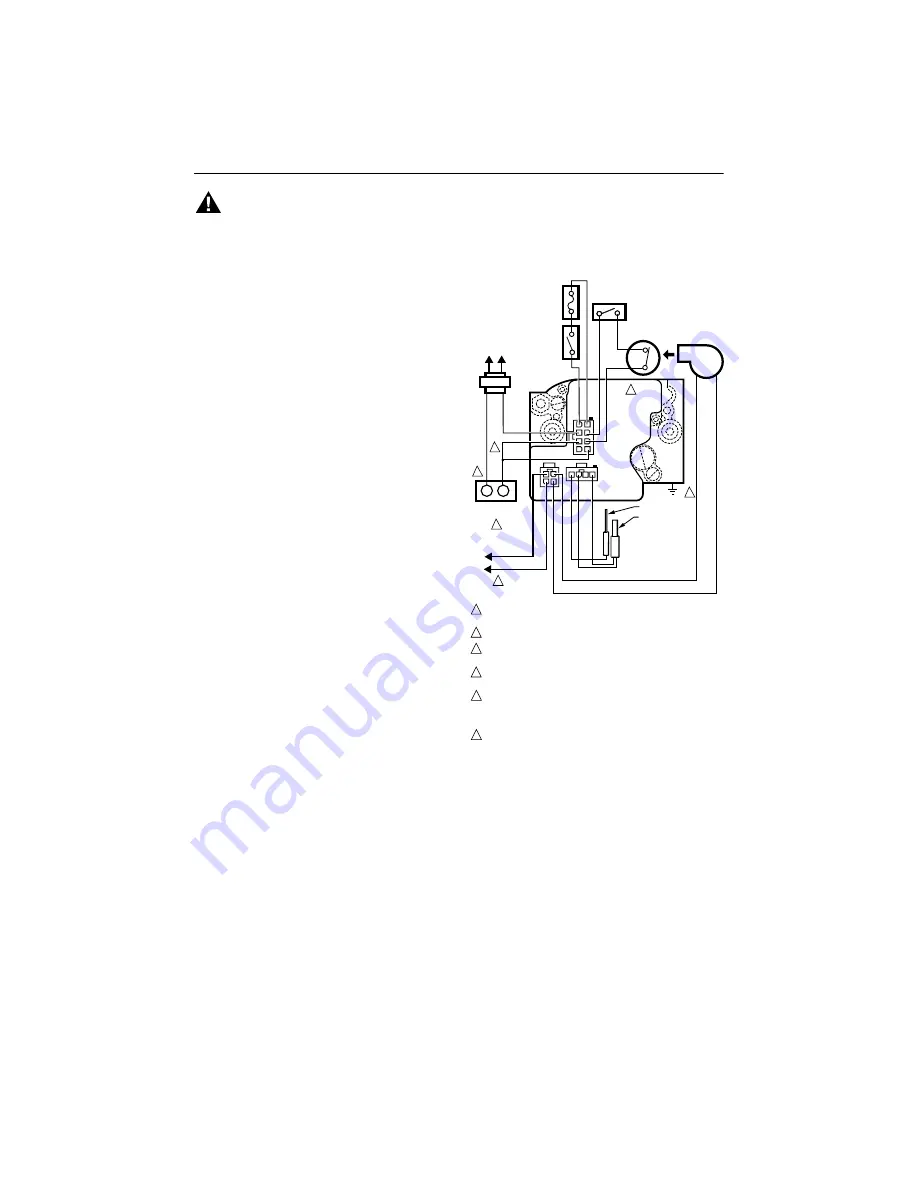
Fig. 9. SV9520 typical wiring connections 

direct to the system thermostat.

C1

C2

C3

LOAD

COMMON

THERMOSTAT

POWER SUPPLY. PROVIDE DISCONNECT MEANS AND OVERLOAD 
PROTECTION AS REQUIRED.

CONNECT 120V (HOT) LEAD AS SHOWN.

APPLIANCE CHASSIS MUST HAVE RELIABLE CONNECTION TO
 EARTH GROUND.

DATA AND R LINES MUST BE CONNECTED TO W ON THERMOSTAT 
FOR PROPER SYSTEM OPERATION.

THERMOSTAT MUST HAVE ZERO OFF-STATE CURRENT DRAW. 
MECHANICAL SWITCH THERMOSTATS RECOMMENDED.  TRIAC
SWITCH THERMOSTATS OR POWER-STEALING THERMOSTATS 
ARE NOT RECOMMENDED.

IN THIS APPLICATION, POSTPURGE FUNCTION IS NOT AVAILABLE
AND THE LED FUNCTIONS ONLY DURING A CALL FOR HEAT.

1

4

5

6

6

3

2

2

5

4

1

M17608

AIR

PROVING

SWITCH

NEUTRAL

HOT

L2

L1
(HOT) 

TO
120 VAC, 60 HZ 
POWER SUPPLY

ROLL-OUT

SWITCH

LIMIT

SWITCH

COMBUSTION
AIR BLOWER

R

W

R

C

AIR

DATA

40 VA
TRANSFORMER

L1

L2

SV9520

HOT 
SURFACE 
IGNITER

FLAME ROD

3

AUXILIARY
LIMIT SWITCH
(OPTIONAL)

1

1
2

5
6

7
8

3

2

2

3

3

1

4

4

4

Summary of Contents for SmartValve SV9520H

Page 1: ... control is removed when the thermostat call for heat ends This system is suitable for a wide range of fan assisted combustion gas fired appliances including furnaces rooftop furnaces boilers unit heaters infrared heaters water heaters and commercial cooking appliances The specific application of the SmartValve System is the responsibility of the appliance manufacturer See Table 2 for temperature ...

Page 2: ...pressure drop Table 4 Gas Capacity Conversion Factor Table 5 Adapter Flange Part Numbers a Flange kits include one flange one O ring and four mounting screws PLANNING THE INSTALLATION WARNING Fire or Explosion Hazard Can cause property damage severe injury or death Follow these warnings exactly 1 Plan the installation as outlined below 2 Plan for frequent maintenance as described in the Maintenanc...

Page 3: ...l Shock Hazard Can cause serious injury or death Disconnect power supply before installation More than one disconnect may be necessary Connect the appliance chassis to earth ground Make sure the 120 Vac neutral line and earth ground are electrically common at the breaker box INSTALLATION When Installing this Product 1 Read these instructions carefully Failure to follow them could damage the produc...

Page 4: ...he control after completing the installation includes leak testing the adapters and screws If you use a wrench on the valve after the flanges are installed use the wrench only on the flange not on the control See Fig 5 Location The SV9520H is mounted in the appliance vestibule on the gas manifold CAUTION Equipment Damage Hazard Water can damage equipment and wiring Do not locate where water can dr...

Page 5: ...ol inlet and outlet if necessary 6 Connect the pipe to the ignition system control inlet and outlet Use a wrench on the square ends of the ignition system control If a flange is used place the wrench on the flange rather than on the ignition system control Refer to Fig 4 and 5 Fig 4 Top view of ignition system control Fig 5 Proper use of wrench on ignition system control with and without flanges P...

Page 6: ...commonality STARTUP AND CHECKOUT Ignition System Control Switch Settings Ignition system control switch settings are as follows OFF prevents main gas flow through the ignition system control ON permits gas to flow through the control body At the appropriate time in the appliance operation main gas can flow to the main burner NOTE Controls are shipped with the ignition system control switch in the ...

Page 7: ...river turn the inner adjustment screw clockwise to increase or counterclockwise to decrease the gas pressure to the burner c Always replace the cap screw and tighten firmly to prevent gas leakage 4 If the desired outlet pressure or flow rate cannot be achieved by adjusting the ignition system control check the ignition system control inlet pressure using a manometer at the ignition system control ...

Page 8: ...ening model to assure lightoff at step pressure Model Type Type of Gas Nominal Inlet Pressure Range Factory Set Nominal Outlet Pressure Setting Range Step Full Rate Step Full Rate Slow NAT 5 0 to 7 0 3 5 3 0 to 5 0 LP 12 0 to 14 0 10 0 8 0 to 12 0 Model Type Type of Gas Nominal Inlet Pressure Range Factory Set Nominal Outlet Pressure Setting Range Step Full Rate Step Full Rate Slow NAT 1 2 to 1 7 ...

Page 9: ...ls 3 Observe LED indicator on SV9520 check and repair the system as noted in Table 9 4 After LED flash code analysis and appliance repair are complete turn thermostat below room temperature for 10 seconds turn the thermostat above room temperature to initiate a new call for heat 5 Observe the ignition sequence comparing it to the Sequence of Operation shown in Fig 11 Allow the new ignition sequenc...

Page 10: ...tion comparing it to the Sequence of Operation shown in Fig 11 Allow the ignition sequence to proceed until the appliance lights or an abnormal or unexpected event is observed Be sure to wait long enough for one of the LED diagnostic codes to flash 7 Observe the LED indicator on the SmartValve check and repair the system as noted in Table 10 8 After analysis and repair are complete turn off applia...

Page 11: ...reset the safety control 2 Disconnect all electric power to the appliance 3 Remove the ignition system control access panel 4 Move the ignition system control switch to the OFF position 5 Wait five minutes to clear out any unburned gas If you then smell gas STOP Follow Step 1 in the Warning above If you do not smell gas continue with the next step 6 Move the ignition system control switch to the O...

Page 12: ...R PROVING SWITCH PROVED CLOSED WITHIN 30 SECONDS COMBUSTION AIR BLOWER OFF MAIN VALVE CLOSES COMBUSTION AIR BLOWER OFF AFTER POST PURGE 1 HOUR AUTO LOCKOUT RESET DELAY MAIN VALVE CLOSES COMBUSTION AIR BLOWER OFF AFTER POST PURGE CIRCULATING AIR FAN OFF AFTER DELAY WAIT FOR NEXT CALL FOR HEAT FAILED TRIALS FOR IGNITION LESS THAN FOUR DURING THIS IGNITION SEQUENCE NO NO YES YES YES NO NO MAIN VALVE ...

Page 13: ...hes Limit string open Combustion air blower is energized If control system includes ST9160 Electronic Fan Timer the heat speed circulating air fan will be energized System waits for limit string to close then initiates a new ignition sequence 1 Open high temperature or auxiliary limit switch 2 Open manual reset or auto reset burner rollout switch in the limit circuit 3 Limit and rollout switch cir...

Page 14: ... inducer wiring 2 Low line voltage power supply 3 Airflow proving switch operation tubing wiring 4 Obstructions or restrictions in appliance air intake or exhaust flue system that prevent proper combustion airflow 5 Other devices such as auxiliary limits in the airflow proving circuits 6 4 Flashesa b Soft Lockout Recycle count exceeds 5 on this call for heat last failure was Limit Circuit Opened D...

Page 15: ...hes Limit string open Combustion air blower is energized If control system includes ST9160 Electronic Fan Timer the heat speed circulating air fan will be energized System waits for limit string to close then initiates a new ignition sequence 1 Open high temperature or auxiliary limit switch 2 Open manual reset or auto reset burner rollout switch in the limit circuit 3 Limit and rollout switch cir...

Page 16: ... 2 Low line voltage power supply 3 Airflow proving switch operation tubing wiring 4 Obstructions or restrictions in appliance air intake or exhaust flue system that prevent proper combustion airflow 5 Other devices such as auxiliary limits in the airflow proving circuits 6 4 Flashesa b Soft Lockout Recycle count exceeds 5 on this call for heat last failure was Limit Circuit Opened During Run 1 Ope...

Reviews: