Honeywell
• 31
P
OWER
CABLING
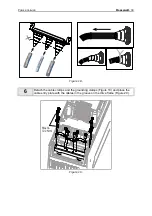
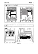
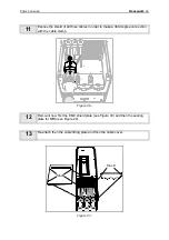
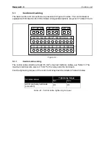
Figure 20.
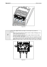
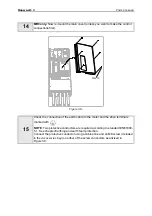
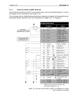
Figure 21.
7
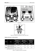
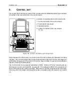
Connect the stripped cables (see Figure 14 and Figure 18) as shown in
Figure 21.
•
Expose the shield of all three cables in order to make a 360-degree con-
nection with the cable clamp (1).
•
Connect the (phase) conductors of the supply, brake and motor cables
into their respective terminals (2).
•
Form the rest of the cable shield of all three cables into “pigtails” and make
a grounding connection with a clamp as shown in Figure 21 (3). Make the
pigtails just long enough to reach and be fixed to the terminal - not longer.
L1L2L3
R+ R- U V W
1
2
3
3


