Honeywell S8701 Installation Instructions Manual Download Page 9

69-1174

9

S8701/S8702 DIRECT SPARK IGNITION CONTROLS

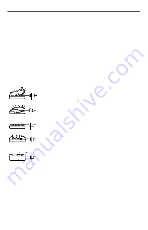
CHECK BURNER FLAME CONDITION

NOISY LIFTING FLAME

BURNER

WAVING FLAME

SMALL BLUE FLAME

LAZY YELLOW FLAME

GOOD RECTIFYING FLAME

1 IN. (25.4 MM)

1/4 TO 1/2 IN. (6.4 TO 12.7 MM)

M18055

CHECK FOR:
•  HIGH GAS PRESSURE
•  EXCESS PRIMARY AIR 
   OR DRAFT

CHECK FOR:
•  POOR DRAFT
•  EXCESS DRAFT
•  HIGH VELOCITY OR
   SECONDARY AIR
INSTALL SHIELD IF NECESSARY.

CHECK FOR:
•  CLOGGED PORTS OR
   ORIFICE FILTER
•  WRONG SIZE ORIFICE

CHECK FOR 
LACK OF AIR FROM:
  •  DIRTY PRIMARY 
     AIR OPENING
  •  LARGE PORTS 
     OR ORIFICES

Low or Unsteady Flame Current

If the current to the S8701/S8702 is less than 1.0 

µ

A or is

unsteady, check the burner flame, flame sensor location
and electrical connections as follows:

Burner Flame

The flame sensor must be constantly immersed in flame.
Check burner flame conditions as shown in Fig. 8.

Flame Sensor

The flame signal is best when about 1 inch. (25 mm) of
flame rod is immersed in the burner flame. A bent flame
rod, bent mounting bracket or cracked ceramic insulator
can affect flame signal. Replace flame sensor if necessary.

Electrical Connections and Shorts

Connections at the flame sensor must be clean and tight. If
wiring needs replacement, use moisture resistant no. 18
AWG wire rated for continuous duty up to 105

°

C (221

°

F).

Fig. 8. Check Burner Flame Conditions.

Checkout After Service

Perform the following steps before leaving the job (de-
scribed in the CHECKOUT section).

START SYSTEM

TRIAL FOR IGNITION PERIOD CHECK

SAFETY LOCKOUT RESET

Also perform any other checks recommended by the
heating appliance manufacturer if system components
other than the S8701 or S8702 were serviced.

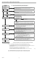
TROUBLESHOOTING GUIDE

Start the system by setting the thermostat or temperature
control to call for heat. Observe the system response and
establish the type of malfunction or deviation from normal
operation by using the troubleshooting guide. After any
maintenance or repair, the troubleshooting sequence
should be repeated until normal system operation is
obtained.

Summary of Contents for S8701

Page 1: ...intenance section Review the following conditions that can apply to your specific installation and take the precautionary steps suggested Frequent Cycling This control is designed for use on commercial cooking appliances that typically cycle 400 times a day year round Perform a monthly checkout Water or Steam Cleaning If a control gets wet replace it If the appliance is likely to be cleaned with w...

Page 2: ...shielding should be provided by the appliance manufacturer verify proper air circulation is maintained when the appliance is installed Table 2 S8701 S8702 Ambient Temperature Ratings IMPORTANT If this is a replacement application follow the appliance manufacturer s instructions if avail able The manufacturer usually provides wiring diagrams start up and checkout instructions and the service proced...

Page 3: ...COMBINATION GAS CONTROL 2 0A MAX TEMPERATURE CONTOLLER LIMIT CONTROLLER TRANSFORMER M16232A FLAME SENSE ALARM VALVE GND VALVE GND 24 Vac GND 24 Vac BURNER GND SPARK ALARM IF USED Fig 2 S8701 Wiring Diagram Minimum VA Rating 24V transformer Total Valve Current in amperes S8701 S8702 in amperes 20 up to 0 6 0 15 30 0 6 to 1 0 0 15 40 1 0 to 1 4 0 15 55 1 4 to 2 0 0 15 Wiring General Precautions 1 Ch...

Page 4: ...d checkout procedures for other system components NOTE If one of the system components fail the S8701 S8702 will either not operate or it will go into safety lockout depending on the type of failure If the system does not perform as outlined in Start System and Check Trial for Ignition steps below refer to the SERVICE section to deter mine the cause Gas Leak Test If the gas control has been replac...

Page 5: ...rners for S8702 Shuts off spark after burner is lit The S8701 and S8702 are powered by a 24 Vac trans former and activated when the temperature control requests heat Operation is as follows When the S8701 S8702 control is activated by the temperature control s request for heat S8701 S8702 controls perform a safe start check that determines proper operation of the control before beginning the norma...

Page 6: ...BE SENSED AT BOTH BURNERS ON S8702 SPARK GENERATOR IS SHUT OFF LOCKOUT TIMER IS RESET IF FLAME CURRENT IS NOT SENSED B D J AND K MODELS GO INTO LOCKOUT AFTER ONE 1 TRIAL FOR IGNITION PERIOD LED IN ON SYSTEM MUST BE RESET MAIN BURNER OPERATION UNIT MONITORS BURNER FLAME CURRENT LOSS OF FLAME SPARK GENERATOR IS POWERED B D J AND K MODELS GO INTO LOCKOUT AFTER ONE 1 TRIAL FOR IGNITION PERIOD LED IS O...

Page 7: ...rol setpoint 5 F 3 C above room temperature Return setpoint to normal temperature setting or by re applying 24 Vac power to the S8701 S8702 control 5 Check ceramic insulator on flame sensor spark igniter or igniter sensor A cracked insulator will allow current to leak to ground Replace device if insulator is cracked START PREPURGE L AND M MODELS ONLY SAFE START CHECK TRIAL FOR IGNITION MAIN BURNER...

Page 8: ... they are clean and tight Grounding Connections A common ground is required for the burner spark igniter or igniter sensor mounting bracket the 24 Vac GND terminal and the GND burner terminal of the S8701 S8702 If ground is poor or erratic safety shutdown may occur occasionally even though operation is normal at time of checkout Therefore if nuisance shutdowns have been reported be sure to check g...

Page 9: ...e rod is immersed in the burner flame A bent flame rod bent mounting bracket or cracked ceramic insulator can affect flame signal Replace flame sensor if necessary Electrical Connections and Shorts Connections at the flame sensor must be clean and tight If wiring needs replacement use moisture resistant no 18 AWG wire rated for continuous duty up to 105 C 221 F Fig 8 Check Burner Flame Conditions ...

Page 10: ...CONTROL IF OKAY REPLACE GAS CONTROL NOTE IF UNIT GOES INTO LOCKOUT RESET SYSTEM CHECK CONTINUITY OF SENSOR CABLE S AND GROUND WIRES NOTE IF GROUND IS POOR OR ERRATIC SHUTDOWNS MAY OCCUR OCCASIONALLY EVEN THOUGH OPERATION IS NORMAL AT TIME OF CHECKOUT CHECK FOR EXCESSIVE HEAT AT SENSOR INSULATOR S TEMPERATURE ABOVE 1000 F 538 C CAUSES SHORT TO GROUND IF CHECKS ARE OKAY REPLACE UNIT NOTE IF UNIT GOE...

Page 11: ...69 1174 11 S8701 S8702 DIRECT SPARK IGNITION CONTROLS ...

Page 12: ...neywell Limited Honeywell Limitée 155 Gordon Baker Road North York Ontario M2H 3N7 69 1174 L C 4 99 Printed in Mexico Home and Building Control Honeywell Inc Honeywell Plaza P O Box 524 Minneapolis MN 55408 0524 www honeywell com ...

Reviews: