


S05, S10, S20 SERIES SPRING RETURN DIRECT COUPLED ACTUATORS
63-2607—08
6
NOTE: The shaft coupling location determines the
travel span.
EXAMPLE:Setting shaft coupling to an approximate
fail-safe position of 35 degrees (as indicated
on the housing) limits stroke to 60 degrees.
4.
Install the shaft coupling at this position.
5.
Replace the retainer clip on the shaft coupling using the
groove of the coupling.
6.
If necessary, replace the holder and position indicator on
the shaft coupling.
Fig. 5. Stroke reduction.
Adjustable Zero and Span
(Enhanced Modulating Models
only
)
These actuators have the capability of adjustable zero and
span. Fig. 4 shows the dials. These dials are present only on
the Enhanced Modulating models. A basic description of these
dials follows:
— Zero: Sets input voltage to define the 0% angle of rotation. It
is factory set to 0 Vdc, and can be adjusted up to 10 Vdc.
— Span: Adjusts motor response to travel full stroke through
the selected input span. It is factory set to 10 Vdc, and is
adjustable from 2 to 32 Vdc.
SET ADJUSTABLE ZERO AND SPAN
1.
Apply 24 Vac to the actuator.
2.
Turn the zero dial (see Fig. 4) past the desired start
point.
3.
Using either a controller or signal generator, apply an
input signal equal to the start point signal.
4.
Slowly adjust zero toward the minimum setting until the
actuator hub begins to move.
5.
Turn the span dial (see Fig. 4) to the
minimum setting (2 Vdc).
6.
Using either a controller or signal generator, apply an
input signal equal to the desired end point signal.
7.
Allow the actuator to open fully.
8.
Slowly adjust span toward the maximum setting until the
actuator hub moves slightly from fully open.
9.
Carefully adjust span knob toward minimum until the
actuator hub returns to fully open.
Auto-Adapt
When using these actuators for standard stroke applications,
this function can be ignored. When it is desirable to use a
mechanically limited stroke (see Mechanical Stroke Limit
Adjustment section), it is possible to use the Auto-Adapt
feature to rescale the input signal over the new limited stroke.
1.
Rotate actuator control signal dial to Auto-Adapt.
NOTE: The actuator will drive open, then closed to
establish the new open and closed positions.
2.
Return the actuator control signal dial to the desired
input signal position.
Manual Positioning
The actuator can be operated with no power present. Use this
feature during installation or to move and lock the damper or
valve shaft position when there is no power.
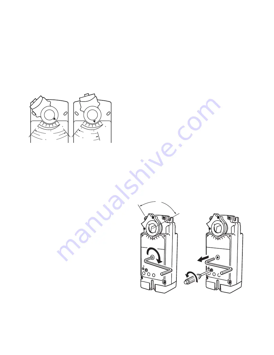
To operate the manual positioning:
1.
If the power is on, turn it off.
2.
Insert supplied hex wrench (key) as shown in Fig. 6.
3.
Rotate key in the direction indicated on the cover.
4.
Once the desired position is reached, hold the key to
prevent the spring return from moving the actuator.
5.
With the key held in place, use a screwdriver to turn the
gear train lock pin in the indicated direction until the
detent is reached.
NOTE: At the detent, the pin resists further rotation.
6.
Remove the key without rotating it further.
To release the manual positioning with no power present:
1.
Insert supplied key.
2.
Turn key 1/4 turn in the direction indicated on the cover.
3.
Remove key without engaging the gear train lock pin.
4.
The spring will return actuator to the fail-safe position.
NOTE: Once power is restored, the actuator will return
to normal automated control.
Fig. 6. Manual positioning.
DRIVE
SPRING RETURN
90 STROKE
45
M22065
90
0
DRIVE
SP
RIN
G RETURN
60
STROKE
45
90
0
M20955A
ROTATING
LOCKING IN PLACE
95
Summary of Contents for S05 Series
Page 15: ...15 63 2607 08 ...


