


10
EC7830, RM7830A,EC7850A,RM7850A 7800 SERIES RELAY MODULES
66-1092—2
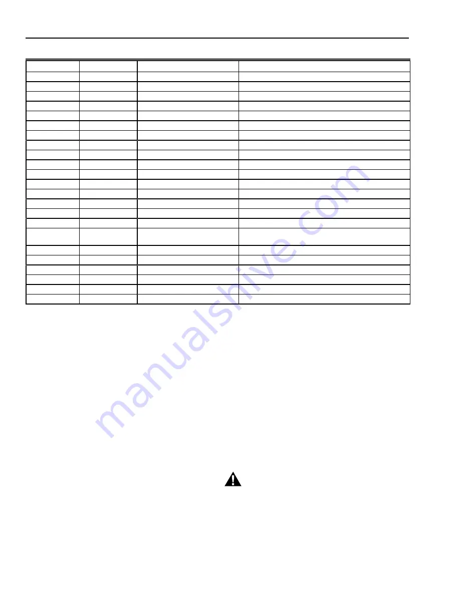
Table 3D. EC7850A Terminal Ratings.
a
See Table 2.
b
2000 VA maximum connected load to relay module.
c
Total load current, excluding Burner/Boiler Motor and Firing Rate Outputs cannot exceed 5A, 25A inrush for 250,000 cycles.
d
Can also be 24 Vac, 3A at PF = 0.5.
e
220/240 Vac to 120 Vac, 10 VA stepdown transformer (not provided) must be used to drive the shutter.
Mounting EC/RM7830A;
EC/RM7850A Relay Module
1. Mount the relay module vertically on the Q7800
Subbase, or mount horizontally with the knife blade
terminals pointing down. When mounted on the
Q7800A, the relay module must be in an electrical
enclosure.
2. When mounting in an electrical enclosure, provide
adequate clearance for servicing, installation and
removal of the relay module, KDM, flame amplifier,
flame amplifier signal voltage probes, electrical signal
voltage probes and electrical connections.
a.
Allow an additional 2 in. (51 mm) below the relay
module for the flame amplifier mounting.
b.
Allow an optional 3 in. (76 mm) minimum on both
sides of the relay module for electrical signal
voltage probes.
3. Make sure no subbase wiring is projecting beyond the
terminal blocks. Tuck in wiring against the back of the
subbase so it does not interfere with the knife blade
terminals or bifurcated contacts.
IMPORTANT
Install the relay module with a plug-in motion rather
than a hinge action.
4. Mount the relay module by aligning the four L shaped
corner guides and knife blade terminals with the
bifurcated contacts on the wiring subbase and securely
tightening the two screws without deforming the plastic.
STATIC CHECKOUT
After checking all wiring, perform this checkout before
installing the relay module on the wiring subbase. These tests
verify that the Q7800 Wiring Subbase is wired correctly and
the external controllers, limits, interlocks, actuators, valves,
transformers, motors and other devices are operating
properly.
WARNING
Fire or Explosion Hazard.
Can cause property damage, severe injury
or death.
Close all manual fuel shutoff valves before starting
this test to prevent an explosion.
Terminal No.
Abbreviation
Description
Ratings
G
Flame Sensor Ground
a
Earth G
Earth Ground
a
N
Line Voltage Common(Neutral)
3
AL
Alarm (Normally Open)
220/230/240 Vac, 1A, 10A inrush for 5000 cycles.
4
L1
Line Voltage Supply (L1)
220 to 240 Vac (+10/-15%), 50/60 Hz (
±
10%).
b
5
FAN
Burner/Blower Motor
220/230/240 Vac, 4A at PF = 0.5, 20A inrush.
6
RT
Limits and Burner Control
220/230/240 Vac, 1 mA.
7
LD2
Airflow Switch Input
220/230/240 Vac, 5A.
8
PV1
Pilot Valve 1 (Interrupted)
220/230/240 Vac, 4A at PF = 0.5, 20A inrush.
c
9
M V
Main Fuel Valve
220/230/240 Vac, 4A at PF = 0.5, 20A inrush.
c
10
IGN
Ignition
220/230/240 Vac, 2A at PF = 0.2.
c
F(11)
Flame Signal
136 to 220 Vac, current limited.
12
HI
Firing Rate High Fire
220/230/240 Vac, 0.5A at PF = 0.5.
d
13
COM
Firing Rate Common
220/230/240 Vac, 0.5A at PF = 0.5.
d
14
MOD
Firing Rate Modulate
220/230/240 Vac, 0.5A at PF = 0.5.
d
15
LO
Firing Rate Low Fire
220/230/240 Vac, 0.5A at PF = 0.5.
d
16
Alarm (normally closed)
220/230/240 Vac, 1A, 10A inrush for 6000 cycles;
carry 5A for 250,000 cycles.
17
ES2
Preignition Interlock Input
220/230/240 Vac, 1 mA.
18
ES1
Low Fire Switch Input
220/230/240 Vac, 1 mA.
19
ES3
High Fire Switch Input
220/230/240 Vac, 1 mA.
20
LOS
Lockout Input
220/230/240 Vac, 1 mA.
21
PV2
Pilot Valve 2 (Intermittent)
220/230/240 Vac, 4A at PF = 0.5, 20A inrush.
c
22
SHTR
Shutter
Shutter drive for dynamic self-check flame sensor.
e