


R8182D,E,F,H,J COMBINATION PROTECTORELAY™ AND HYDRONIC HEATING CONTROLS
68-0105—2
2
ORDERING INFORMATION
When purchasing replacement and modernization products from your TRADELINE® wholesaler or distributor, refer to the
TRADELINE® Catalog or price sheets for complete ordering number.
If you have additional questions, need further information, or would like to comment on our products or services, please write or
phone:
1.
Your local Home and Building Control Sales Office (check white pages of your phone directory).
2.
Home and Building Control Customer Relations
Honeywell, 1885 Douglas Drive North
Minneapolis, Minnesota 55422-4386
In Canada—Honeywell Limited/Honeywell Limitée, 35 Dynamic Drive, Scarborough, Ontario M1V 4Z9.
International Sales and Service Offices in all principal cities of the world. Manufacturing in Australia, Canada, Finland, France,
Germany, Japan, Mexico, Netherlands, Spain, Taiwan, United Kingdom, U.S.A.
SPECIFICATIONS
IMPORTANT
The specifications given in this publication do not
include normal manufacturing tolerances. Therefore,
this unit may not exactly match the listed
specifications. Also, this product is tested and
calibrated under closely controlled conditions, and
some minor differences in performance can be
expected if those conditions are changed.
TRADELINE® Models:
TRADELINE® models are selected
and packaged for ease of handling, ease of stocking, and
maximum replacement value. TRADELINE® model
specifications are the same as those of standard models
except as noted below.
TRADELINE® Models Available:
R8182D Combination Protectorelay™ Primary Control and
Aquastat® Controller.
R8182H Combination Protectorelay™ Primary Control and
Aquastat® Controller.
Additional Features:
• Well not included. To order wells or well adapters, refer to
form 68-0040, Wells and Fittings for Temperature
Controllers, for part numbers and descriptions.
• Heat-conductive compound supplied for better bulb
response in oversized well.
• Field addable stops for Aquastat® Controller.
• Conversion to R8182E or F.
• TRADELINE® pack with special instructions.
• Wire nut.
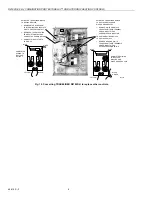
Mounting Means:
R8182D,E,F: Case clamps to horizontal immersion well
installed through boiler wall.
R8182H,J: Mounts on standard 4 x 4 inch junction box.
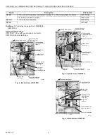
Dimensions:
Refer to Fig. 1 and 2.
Table 1. Standard Models:
a
Auxiliary ZC and ZR terminals can be used to provide circulator zone control through an R845A Switching Relay.
Electrical Ratings:
Power Supply: 120 Vac, 60 Hz.
Ignition: 360 VA in addition to motor load rating.
Maximum Power Consumption:
R8182D,E,H and J: 9W.
R89182F: 5.5W.
Burner Circulator Contact Rating: 4.4A full load; 26.4A locked
rotor at 120 Vac.
Safety Switch Timing:
Approximately 45 seconds.
Flame Detector Required:
C554A Cadmium Sulfide Flame
Detector (ordered separately).
Thermostat Required:
24V, 2-wire thermostat such as the
T87F.
Model
Switching
Adjustable Control Range
Differential
°F
°C
°F
°C
R8182D
a
High Limit, Spst
130 to 240
54 to 116
10 Fixed
6 Fixed
High Limit/Circulator, Spdt
110 to 220
43 to 104
10 to 25 Adj
6 to 14 Adj
R8182E
a
High Limit, Spst
180 to 240
82 to 116
15 Fixed
8 Fixed
R8182F
High Limit, Spst
130 to 240
54 to 116
10 Fixed
6 Fixed
Circulator, Spst
110 to 220
43 to 104
10 Fixed
6 Fixed
R8182H
a
Remote Bulb
High Limit, Spst
130 to 240
54 to 116
10 Fixed
6 Fixed
Low Limit/Circulator, Spdt
110 to 220
43 to 104
10 to 25 Adj
6 to 14 Adj
R8182J
a
Remote Bulb
High Limit, Spst
180 to 240
82 to 116
15 Fixed
8 Fixed
Summary of Contents for R8182D
Page 18: ...68 0105 2 18 ...
Page 19: ...19 68 0105 2 ...