


R7824, R7847, R7848, R7849, R7851, R7852, R7861, R7886 AMPLIFIERS FOR 7800 SERIES AND R7140 RELAY MODULES
65-0109—14
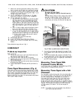
6
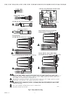
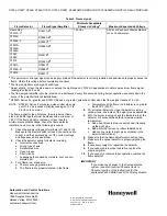
Fig. 3. Flame detector wiring.
BLUE
YELLOW
WHITE
WHITE
WHITE
WHITE
BLACK
BLACK
F
G
22
L2
L1
L2
M27852
BLUE
BLUE
WHITE
WHITE
F
F
G
G
BLUE
WHITE
F
G
INFRARED (C7915)
ULTRAVIOLET (C7027/C7035/C7044)
OPTICAL C7927A
SOLID STATE SELF-CHECKING
ULTRAVIOLET (C7012E,F)
1
1
2
F
G
4
5
3
L2
C7076A,D ULTRAVIOLET DETECTOR
5
22
6
SHUTTER
G
SHUTTER
F
1
8
2
7
7800 SERIES
L1
L2
3a
3b
REMOTE
SENSOR
2b
2a
EARTH
GROUND
C7076A
OR
C7076D
TERMINAL
BLOCK
L2 (COMMON)
L1 (HOT)
G
F
X
X
FLAME ROD
1
!
!
CAUTION: EQUIPMENT DAMAGE HAZARD. INCORRECT WIRING POLARITY CAN DAMAGE OR DESTROY UV SENSING TUBES.
CONNECT FLAME DETECTOR WIRES ACCORDING TO FOOTNOTES 1 AND 2 TO PREVENT UV SENSING TUBE DAMAGE.FLAME DETECTOR
LEADS ARE COLOR CODED. THE BLUE LEAD MUST BE CONNECTED TO THE F TERMINAL AND THE WHITE MUST BE CONNECTED TO
THE G TERMINAL. THE UV SENSING TUBE IS POLARITY SENSITIVE.
FLAME DETECTOR LEADS ARE COLOR CODED. THE BLUE LEAD MUST BE CONNECTED TO THE F TERMINAL AND THE YELLOW MUST
BE CONNECTED TO THE G TERMINAL. THE UV SENSING TUBE IS POLARITY SENSITIVE.
CAUTION: EQUIPMENT DAMAGE HAZARD. INCORRECT VOLTAGE CAN DAMAGE SHUTTER MECHANISM ONLY ON EC7800 SERIES
RELAY MODULES.
INSTALL A 200/220/240 VAC TO 120 VAC, 10VA MINIMUM, STEPDOWN TRANSFORMER (NOT PROVIDED) TO DRIVE
THE SHUTTER MECHANISM.
DO NOT USE 0.8/1 SECOND FFRT AMPLIFIER WITH C7012A,C FLAME DETECTOR.
GND (GREEN) LEAD WIRE ON C7961E ONLY.
2
3
4
5
4
3
3
3
BLUE
YELLOW
WHITE
WHITE
RED
BLACK
F
G
22
SOLID STATE SELF-CHECKING
ULTRAVIOLET (C7024E,F – E SHOWN)
2
L2
3
L2
BLUE
YELLOW
BLACK
BLACK
F
G
L1
L2
GREEN
GND
SOLID STATE
ULTRAVIOLET (C7012A,C, C7961E)
2
5
BLUE
YELLOW
F
G
22
N
SELF-CHECKING ULTRAVIOLET (C7061A)
2


