10
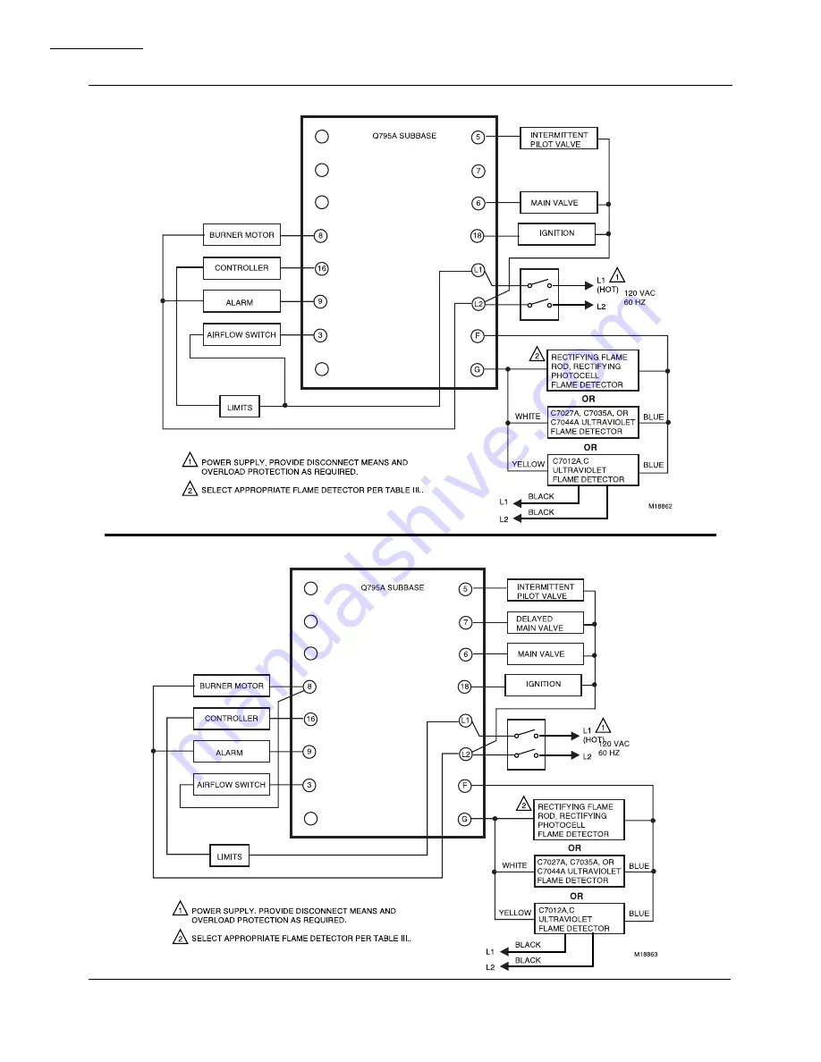
Fig. 7—Wiring the R7795A,B with intermittent pilot.
Fig. 8—Wiring the R7795C,D with interrupted pilot.
R7795A,B,C,D
INSTALLATION
Page 1: ...odels Safe start feature prevents start up with lockout if flame or a flame simulating failure exists Recycleorlockoutonflamefailureisfieldselectable Safety switch must be manually reset after lockout Meets Underwriters Laboratories Canadian Stan dards Association and Factory Mutual Approved standards Integral solid state color coded flame amplifiers R7795A Cforultravioletdetectionsystems purple R...
Page 2: ...dditional questions need further information or would like to comment on our products or services please write or phone 1 Your local Honeywell Home and Building Control Sales Office check white pages of phone directory 2 Home and Building Control Customer Satisfaction Honeywell Inc 1885 Douglas Drive North Minneapolis Minnesota 55422 4386 612 951 1000 In Canada Honeywell Limited Honeywell Limitée ...
Page 3: ...tor Plug for older W136A Test Meters 123514A Flame Simulator for rectification systems 123514B Flame Simulator for ultraviolet systems Q624A Solid State Spark Generator Q795A Wiring Subbase ST795A Plug in Purge Timer models available with 1 5 7 10 30 60 and 90 second timings FSP5004A with adapter for operational check of the R7795 R1061012 Ignition Cable for ignition installations in high temperat...
Page 4: ...ow switch recloses 3 PILOT FLAME ESTABLISHING PERIOD At the end of prepurge ST795A timed out the 1K relay pulls in energizing the ignition transformer termi nal 18 and the intermittent pilot valve terminal 5 This starts the ten or four second pilot flame establishing period Safety shutdown and lockout will occur if pres ence of flame is not proven within TensecondsiftheORANGEjumperisnotclipped Fou...
Page 5: ...TROLLER LIMIT S FLAME AMPLIFIER SOLID STATE LOGIC CKT 3K3 3K1 1K2 F1 S SW S SW 3K 1K 1K 2K1 2K1 INTERRUPTED PILOT VALVE MAIN FUEL VALVE BURNER MOTOR IGNITION TRANSFORMER FLAME DETECTOR FLAME DETECTOR BASIC DIAGRAM OF THE R7795B LINE VOLTAGE ALARM 5 7 6 18 L1 L2 F G G 8 16 9 3 2K ST795A 120 Vac 60 HZ L1 HOT L2 LINE VOLTAGE AIRFLOW SWITCH CONTROLLER LIMIT S FLAME AMPLIFIER SOLID STATE LOGIC CKT 3K3 ...
Page 6: ... proven within TensecondsiftheORANGEjumperisnotclipped Four seconds if the ORANGE jumper is clipped If the RUN TEST switch is moved to the TEST posi tion during the pilot flame establishing period the se quence is stopped in trial for pilot flame The safety switch heater is energized during this pilot flame establishing period whenever flame is not present Safety shutdown and lockout will occur if...
Page 7: ...LIMIT S FLAME AMPLIFIER SOLID STATE LOGIC CKT 3K3 3K1 1K2 F1 S SW S SW 3K 4K1 4K2 2K1 2K1 INTERRUPTED PILOT VALVE DELAYED MAIN VALVE MAIN FUEL VALVE BURNER MOTOR IGNITION TRANSFORMER FLAME DETECTOR FLAME DETECTOR BASIC DIAGRAM OF THE R7795D LINE VOLTAGE ALARM 5 7 6 18 L1 L2 F G G 8 16 9 3 2K 4K ST795A RUN TEST SWITCH 120 Vac 60 HZ L1 HOT L2 LINE VOLTAGE AIRFLOW SWITCH CONTROLLER LIMIT S FLAME AMPL...
Page 8: ... THIS SWITCH IS IN THE RUN POSITION BEFORE LEAVING THE INSTALLATION Installation WHEN INSTALLING THIS PRODUCT 1 Read these instructions carefully Failure to fol low them could damage the product or cause a hazardous condition 2 Check the ratings given in the instructions and on the product to make sure the product is suitable for your application 3 Installer must be a trained experienced flame saf...
Page 9: ... in a salt bath for one minute without breakdown It is rated at 200 F 93 C for continuous duty and up to 300 F 175 C for intermittent use WIRING HOOKUPS The typical wiring hookups in Figs 7 and 8 show the connections to the Q795A Subbase INSTALLING THE R7795 1 Remove the cover from the R7795 2 Position the R7795 over the terminal barrier strips as shown in Fig 1 and press the R7795 onto the subbas...
Page 10: ...10 Fig 7 Wiring the R7795A B with intermittent pilot Fig 8 Wiring the R7795C D with interrupted pilot R7795A B C D INSTALLATION ...
Page 11: ...e location of component parts Remove the device cover by loosening the screw WARNING IF FUEL ENTERS THE COMBUSTION CHAMBER FOR MORE THAN A FEW SECONDS WITHOUT IGNITING AN EXPLOSIVE MIXTURE COULD RESULT THE FOLLOWING TIME LIMITS ARE RECOMMENDED Trial for PILOT 10 seconds Trial for MAIN FLAME 5 seconds In any case DO NOT EXCEED THE MANU FACTURER S SPECIFIED NORMAL LIGHT OFF TIME Close the manual mai...
Page 12: ... for the R7795A C models refer to Table 3 If the minimum average current level cannot be ob tained one or more of the following conditions may exist 1 Check the supply voltage at terminals L1 L2 on the wiring subbase Make sure the master switch is closed connections are correct and the power supply is the correct voltage and frequency 2 Check the flame detector wiring for defects including incorre...
Page 13: ...ch and let the system recycle 7 When the pilot ignites measure the flame signal If necessary adjust the flame or detector to give the proper flame signal 8 Recycle the system to recheck lightoff and the pilot flame signal NOTE The next steps require two people one to open the manual main shutoff valve s and one to watch for ignition 9 When entering the main flame ignition trial period make sure th...
Page 14: ...to step 18 a Open the manual second stage oil valve b Restart the system by raising the setpoint of the burner controller c When the first stage burner flame is estab lished watch for the automatic second stage oil valve to open Observe that the second stage flame lights off properly d Make burner adjustments for flame stability and input rating e Shut down the system by lowering the setpoint of t...
Page 15: ...3 12 Repeat steps 5 through 12 until the main burner positively lights with the pilot just causing the Flame Indicator LED to remain on 13 Repeat the main burner lightoff several times with the pilot at turndown 14 When the main burner lights reliably with the pilot at turndown disconnect the manometer or gauge and turn up the pilot to normal 15 If used remove the bypass jumpers from the low fuel ...
Page 16: ...e main burner and pilot flames together unless moni toring only the pilot flame when using intermittent igni tion or only the main burner flame with direct spark ignition Check the signal at both high and low firing rate if applicable Also check the flame failure response time Lower the setpoint of the burner controller and observe the time it takes for the Flame Indicator LED to go out after the ...
Page 17: ...TANT 1 Output terminals MUST NOT BE SHORTED TO L2 Shorted output terminals will cause permanent dam age to the R7795 2 If after performing an applicable troubleshooting procedure proper operation cannot be obtained replace the R7795 except the ST795A Purge Timer unless noted A Relay 3K does not respond to a call for heat 1 Make sure that the safety switch is reset 2 Check the power at terminals L1...
Page 18: ... ignition spark does not occur or the pilot valve does not open 1 Make sure that all manual fuel valves are opened 2 Check the voltage at the pilot or first stage oil valve terminal 5 and the ignition terminal 18 Check must be made before device locks out 3 If the voltage is zero replace the R7795 NOTE If terminals 5 and or 18 are shorted to L2 the R7795 will be permanently damaged This shorted co...
Page 19: ...wellcontactcleanerpartno 132569 DO NOT use any other type of contact cleaner 3 Use the utmost care to avoid bending the contacts or changing the configuration in any way 4 Do not use abrasive materials to clean contacts 5 Do not use hard paper such as a business card to clean contacts If relay contacts must be cleaned use only Honeywell pressurized contact cleaner part no 132569 The Honeywell chem...
Page 20: ...lding Control Helping You Control Your World Honeywell Inc Honeywell Limited Honeywell Limitée 1985 Douglas Drive North 740 Ellesmere Road Golden Valley MN 55422 Scarborough Ontario M1P 2V9 Printed in U S A www honeywell com bbc QUALITY IS KEY ...