Honeywell Prestige THX9421R02 Installation Manual Download Page 8


8


4

Performing initial setup

Initial setup options define the type of system you are installing:

• 

Residential or commercial

• 

Non-zoned or zoned

• 

Used with or without an Equipment Interface Module (THM5421) 

• 

Used with or without the TrueZONE Wireless Adapter (THM4000)

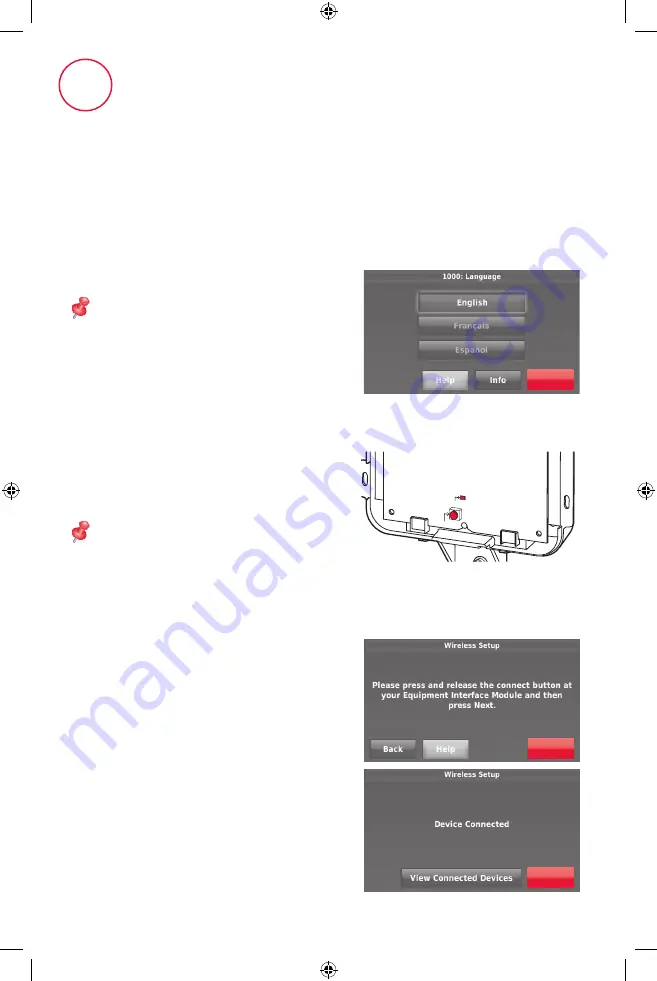
4.2  Link the thermostat to the equipment 

interface module.

4.2a 

Press and quickly release

 the 

CONNECT button on the EIM. 
Make sure the “Connected” light is 
flashing green.

NOTE: 

If the “Connected” light does 

NOT flash green, another system may 
be in the listening mode. Please exit the 
listening mode at the other system and 
then try again.

• 

Green Flashing: In Listening  
Mode - system is ready to add 
RedLINK devices.

• 

Green Steady: RedLINK devices are 
communicating.

• 

Red: RedLINK device(s) are NOT 
communicating. Check EIM and 
RedLINK devices.

4.2b While the “Connected” light is 

flashing green on the EIM, press 

Next

 on the thermostat. After a 

short delay, the screen will display 
Device Connected.

4.1  Follow prompts on the screen to 

select appropriate options.

NOTE: 

If you are connecting the 

thermostat to the TrueZONE Wireless 
Adapter (THM4000), refer to the 
TrueZONE instructions to link the 
thermostat and RedLINK accessories. 
Then go to step 4.5.

Next

CONNECT

CONNEC

TED

Next

Next

69-2739_A.indd   8

11/1/2012   2:33:31 PM

Summary of Contents for Prestige THX9421R02

Page 1: ...Q with Equipment Interface Module Installation Guide TM TM TM OR 2 Wires for Power 2 Wires for Power RedLINK to Equipment Interface Module RedLINK to TrueZONE Wireless Adapter 69 2739_A indd 1 11 1 2012 2 33 23 PM ...

Page 2: ...utdoor sensor USB port Use USB device to load settings and dealer information Reference to key features Password is date code Getting started Follow these basic steps to install this thermostat link it with the equipment interface module EIM and wireless accessories and set installer options 1 Installing the Equipment Interface Module EIM 2 Installing the thermostat 3 Powering optional RedLINK acc...

Page 3: ...ked in the kit 1 Installing the equipment interface module EIM Terminal Designations Conventional System Heat Pump Terminal Description Terminal Description C Common wire from 24 VAC transformer C Common wire from 24 VAC transformer R Power wire from 24 VAC transformer R Power wire from 24 VAC transformer RH Heating power RH Heating power RC Cooling power RC Cooling power W Heat Stage 1 O B Change...

Page 4: ...00R1000 Wireless Adapter for extended wireless range See wiring diagrams on pages 4 5 See wiring diagram below for wiring Dry Contact Devices to display alerts U1 U2 and U3 are normally open dry contacts when set up for a stage of heating or cooling You must install a field jumper if the stage of heating or cooling is powered by the system trans former Do NOT install a field jumper if the stage of...

Page 5: ...N WITH LOW SPEED FAN 24 VAC 120 VAC 1 2 Typical hookup of powered humidifier Typical hookup of non powered humidifier Typical hookup of powered ventilation Typical hookup of powered dehumidifier whole house dehumidifer Typical hookup of variable speed blower for dehumidification in low speed Typical hookup of non powered ventilation Any combination of universal relays U1 U2 U3 can be used They are...

Page 6: ...to the R and C terminals at the EIM or to a separate 24 volt transformer not provided 2 3b Push excess wire back into the wall opening 2 4 Insert coin cell battery Place coin cell battery in thermostat as shown with side up NOTE Coin cell battery saves time and date during a power loss 2 Installing the thermostat R C 1324 Thermostat back view Thermostat back view Wallplate back view Wallplate Wall...

Page 7: ...p 4 5 3 2 Connect gateway to internet and connect to power 3 2a Connect RedLINK Internet Gateway to router or modem with Ethernet cable RJ45 3 2b Connect gateway s power cord to an electrical outlet that is not controlled by a wall switch 3 Powering optional RedLINK accessories Thermostat Wallplate 2 5 Mount thermostat on wallplate Align thermostat to wallplate and snap into place R C 3 2a 3 2b 69...

Page 8: ...e exit the listening mode at the other system and then try again Green Flashing In Listening Mode system is ready to add RedLINK devices Green Steady RedLINK devices are communicating Red RedLINK device s are NOT communicating Check EIM and RedLINK devices 4 2b While the Connected light is flashing green on the EIM press Next on the thermostat After a short delay the screen will display Device Con...

Page 9: ...n on each new RedLINK accessory 4 4b After a short delay up to 20 seconds check the thermostat to confirm the connection of each RedLINK accessory 4 4c Touch Done at the thermostat after all new RedLINK accessories are connected NOTE The thermostat displays a countdown timer while in listening mode If it detects no activity for 15 minutes it exits listening mode Done 4 5 Finish the initial setup F...

Page 10: ... Installer Setup To perform Installer Test To view Data Logs Finding your password You can find the Date Code on the back of the thermostat or 1 Touch Menu 2 Select Dealer Information Dealer Informa on OK 1324 1324 Thermostat back view Password Date Code 69 2739_A indd 10 11 1 2012 2 33 31 PM ...

Page 11: ...CT button on each new RedLINK accessory 5b After a short delay up to 20 seconds check thermostat to confirm the connection of each RedLINK accessory 5c Touch Done at the thermostat after all new RedLINK accessories are connected NOTE Thermostat displays a countdown timer while in listening mode If it detects no activity for 15 minutes it exits listening mode Linking RedLINK accessories to the ther...

Page 12: ...ons 3 Enter password date code and touch Done 4 Select Create Setup or Installer Test 5 Follow prompts on the screen to select the desired setup options or to perform an equipment test Installer Op ons Done Mounting an outdoor sensor 1 Mount the sensor on a vertical exterior wall at least 6 inches below any overhang Choose a location protected from direct sunlight 2 Place sensor securely in bracke...

Page 13: ...ple sensors are selected the thermostat will respond to an average of temperatures detected at each sensor Humidification control If optional remote indoor sensors are installed you can choose which sensor you want to use for humidification control You can use a different sensor for dehumidification Dehumidification control If optional remote indoor sensors are installed you can choose which senso...

Page 14: ...t thermostat information on the USB device select Save to USB When you replace a thermostat you must reset the RedLINK accessories before connecting them to the new thermostat Follow the instructions below At the Portable Comfort Control Press and hold the blank space or arrow in the lower right corner of the screen until the display changes hold for about 4 seconds Press REMOVE then YES to discon...

Page 15: ...0 Mhz frequency range Re Sync Time RedLINK devices re establish communication within 6 minutes after AC power resumes Electrical ratings Terminal Voltage 50 60 Hz Max Current Rating W OB 18 to 30 VAC and 750 mVDC 1 00A Y cooling 18 to 30 VAC 1 00A G fan 18 to 30 VAC 0 50A W2 Aux 1 heating 18 to 30 VAC 0 60A W3 Aux 2 18 to 30 VAC 0 60A Y2 cooling 18 to 30 VAC 0 60A A L A output 18 to 30 VAC 1 00A U...

Page 16: ...URY NOTICE If this product is replacing a control that contains mercury in a sealed tube do not place the old control in the trash Contact the Thermostat Recycling Corporation at www thermostat recycle org or 800 238 8192 for information on how and where to properly and safely dispose of your old thermostat Must be installed by a trained experience technician Read these instructions carefully Fail...

Reviews: