Honeywell PRESSURETROL L404F Product Data Download Page 7

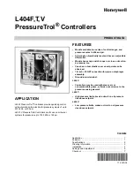
L404F,T,V PRESSURETROL

®

 CONTROLLERS

7

71-2429—06

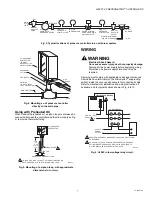
Fig. 12.  view of L404 PressureTrol

®

 Controller.

Scaleplate Adjustment

The L404F,T,V has been carefully calibrated during 

manufacture and should not require recalibration.

However, if recalibration is necessary, remove the cover and 

loosen the setscrews which hold the scaleplate. Adjust the 

plate up or down, as required, to bring the device into 

calibration. Tighten the setscrews securely and replace the 

cover.

CHECKOUT

After the controller has been installed, wired and adjusted, it 

should be tested with the system in operation. First, allow the 

system to stabilize. Then, observe the operation of the 

controller while raising and lowering its setpoint. Pressure 

should increase when the setpoint is raised and decrease 

when the setpoint is lowered.

Also, check the make and break points of the controller. If they 

do not agree with a separate, accurately calibrated pressure 

gauge, a slight adjustment of the scaleplate(s) may be 

necessary.

Use accurate pressure testing equipment when checking out 

the controller. Do not rely on inexpensive gauges. The 

controllers are carefully calibrated at the factory.
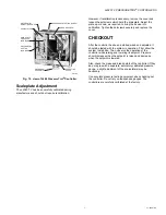
GROUND SCREW

DIFFERENTIAL

ADJUSTING SCREW

SCALEPLATES

DIAPHRAGM

ASSEMBLY

M19640A

OPERATING

LEVER

MAIN SCALE

PRESSURE

INDICATOR

DIFFERENTIAL

SETTING

INDICATOR

PRESSURE ADJUSTING SCREW

Summary of Contents for PRESSURETROL L404F

Page 1: ...ve an adjustable differential Models have snap switch to open or close a circuit on a pressure rise Case has a clear plastic cover so setpoints can be observed 1 4 inch 18 NPT connection for pipe on diaphragm assembly Ground screw terminal L404F Controllers may be used with steam air or noncombustible gases or fluids noncorrosive to the pressure sensing element L404T High pressure limits break a c...

Page 2: ...ating Ranges Subtractive Differentiala Maximum Diaphragm pressure kPa psi kPa psi kPa psi L404F1060 15 to 100 2 to 15 15 to 40 2 to 6 170 25 L404F1078 35 to 350 5 to 50 40 to 100 6 to 14 590 85 L404F1094 140 to 2070 20 to 300 140 to 345 20 to 50 2410 350b L404F1102 70 to 1035 10 to 150 70 to 150 10 to 22 1550 225 L404F1219c 15 to 100 2 to 15 15 to 40 2 to 6 170 25 L404F1243c 35 to 350 5 to 50 40 t...

Page 3: ...ws 4074BWJ Range Stop range stop screw Part No 107194 and wrench Part No 23466 to limit setpoint range Approvals Underwriters Laboratories Inc Listed file no MP466 vol 10 guide no MBPR Canadian Standard Association certified file no LR1620 guide no 400E 0 Fig 1 L404F T V approximate dimensions in inches millimeters in parentheses Operating Range Conversions Subtractive Differential Conversions kg ...

Page 4: ... be suitable and properly pitched to drain all condensation back to the boiler 2 The remote mounting must be solid 3 A steam trap must be used at one end of the piping Boiler Mounting If it is not convenient to mount the L404F adjacent to the pressure gauge install a steam trap at the location recommended by the boiler manufacturer then screw the device directly to the steam trap Location and Moun...

Page 5: ...ng instructions if available and to typical hookups shown in Fig 6 to 10 Fig 6 L404F in low voltage relay circuit MAIN OIL LINE TO OIL BURNER ATOMIZER ATOMIZING MEDIUM AIR OR STEAM MANUAL SHUTOFF VALVE LOW OIL PRESSURE CONTROLLER HIGH OIL PRESSURE CONTROLLER RECIRCULATING VALVE AND SAFETY SHUTOFF VALVE OIL PUMP WITH PRESSURE RELIEF LOW OIL TEMPERATURE STRAINER MANUAL SHUTOFF VALVE M17861 OIL PRESS...

Page 6: ...eration of switch on pressure rise and fall Setpoint Adjustment Turn the pressure adjusting screw on the top of the controller Fig 12 to adjust the setpoint Turn the differential adjusting screw to the desired pressure difference between switch opening and switch closing NOTE When the main scale setting is at the lower end of the operating range the differential range will be less than the differe...

Page 7: ... operation First allow the system to stabilize Then observe the operation of the controller while raising and lowering its setpoint Pressure should increase when the setpoint is raised and decrease when the setpoint is lowered Also check the make and break points of the controller If they do not agree with a separate accurately calibrated pressure gauge a slight adjustment of the scaleplate s may ...

Page 8: ...eywell International Inc 1985 Douglas Drive North Golden Valley MN 55422 Honeywell Limited Honeywell Limitée 35 Dynamic Drive Toronto Ontario M1V 4Z9 customer honeywell com U S Registered Trademark 2010 Honeywell International Inc 71 2429 06 M S Rev 09 10 Printed in U S A ...

Reviews: