

2
|
HD251H Rugged Indoor/Outdoor Fixed Minidome Quick Install Guide
www.honeywell.com/security
+1 800 323 4576 (North America only)
https://www.honeywellsystems.com/ss/techsupp/index.html
© 2014 Honeywell International Inc. All rights reserved. No part of this publication may be reproduced by any
means without written permission from Honeywell. The information in this publication is believed to be accurate
in all respects. However, Honeywell cannot assume responsibility for any consequences resulting from the use
thereof. The information contained herein is subject to change without notice. Revisions or new editions to this
publication may be issued to incorporate such changes.
Document 800-19022 – Rev D – 08/2014
5. Camera Installation
1.
Remove the dome from the
housing base by loosening
the captured screws on the
dome.
2.
Connect the yellow video
output connector to the
video input port on your
monitor/DVR. Connect the
red power connector to
your 12 V DC power
source. Feed the cables
into the hole in the
mounting surface (such as
a ceiling, see graphic).
3.
Install the housing base
onto the mounting surface
using the three mounting
screws provided.
4.
Connect the local video
output cable to the video
output connector on the
camera board, located
behind the lens and gimbal.
Connect the other end of
the video connector to the
monitor you will use while
setting up the camera.
Note
The video output
connector on the
camera board is
located next to the OSD
menu controls that you
can use to make
configuration changes.
5.
While monitoring the
camera picture on the monitor, adjust the camera position (orientation), zoom and
focus settings (as described in the
Camera Positioning, Zoom and Focus Adjustment
section).
6.
Using the connected monitor, make camera configuration changes through the OSD
menus (see the
Configuration Guide
included with your camera for more
information).
7.
Re-install the dome cover to the housing base by aligning the captured screws to the
screw holes, and then tightening the screws.
Video and
power cable
(see the
diagram).
Dome
cover
2nd video
output
connector
Mounting
surface
Housing
base
Mounting
screws
Captured
screws
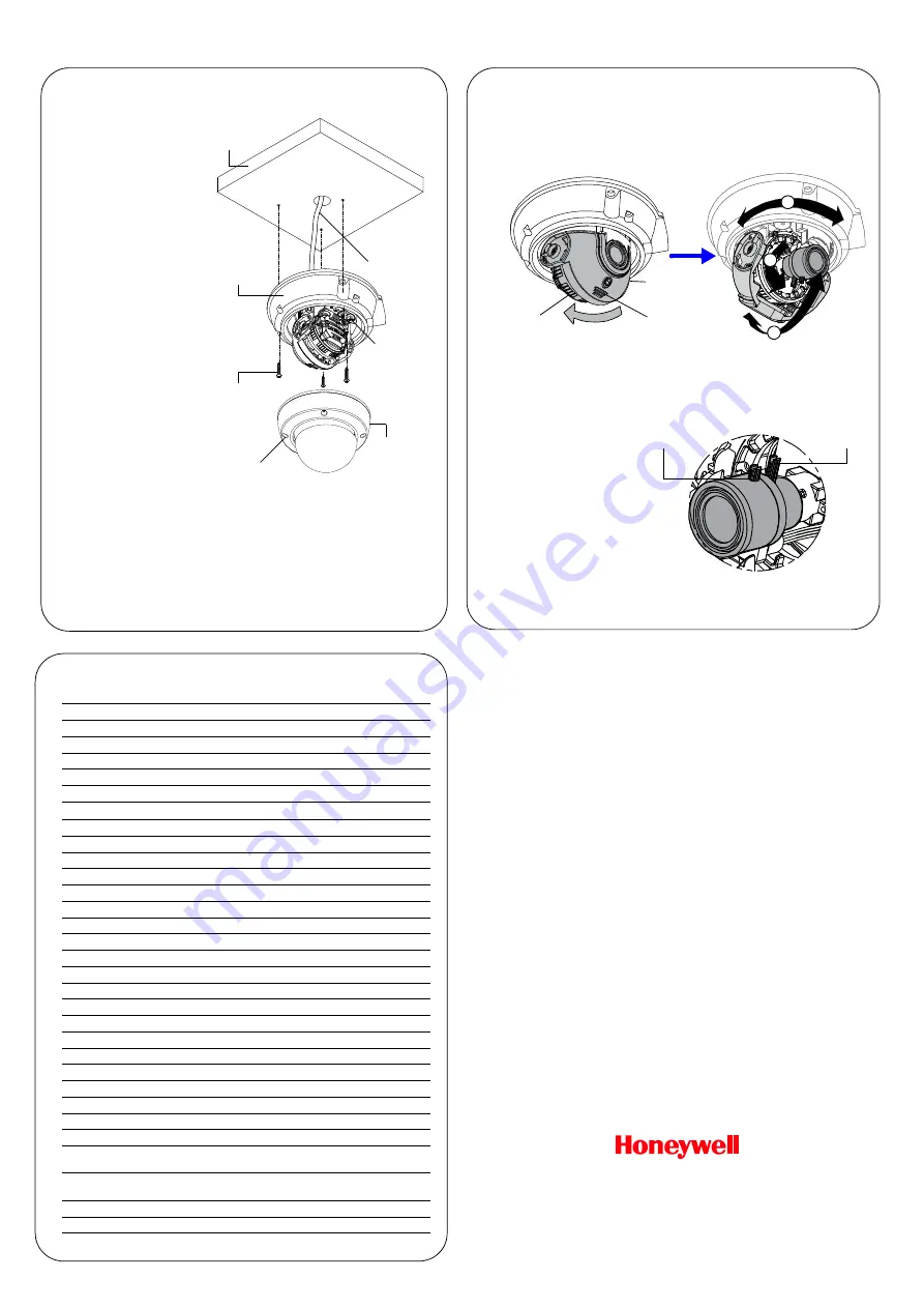
6. Camera Positioning, Zoom and Focus Adjustment
1.
With the dome removed, you can see that the lens is surrounded by a protective
shroud (see the image below).
2.
Use two hands to draw back the shroud from the lens by placing both thumbs on the
upper front section of the shroud with your fingers bracing the back side of the lens
and pushing your thumbs towards your fingers (see the image below).
3.
Position the camera lens and gimbal so that the camera is viewing the required video
scene. Use the connected monitor to check that the field of view is oriented correctly
as you make the adjustments. You can pan the entire camera board and gimbal
(360°, labeled
A
in graphic above). Tilt the camera lens up and down (90°, labeled
B
),
and/or rotate the lens (360°,
C
).
4.
Use the three points of
adjustment (
A
,
B
, and
C
) to
position the camera
correctly.
5.
Use the two levers located
on the lens to adjust zoom
and focus, as needed (see
the image for zoom and
focus lever locations).
6.
When the camera is
correctly positioned,
zoomed and focused, push
the shroud back together
with the lens.
When you push the shroud back together with the lens, this will change the tilt angle that you
have set for the lens (adjustment labeled
B
). When the shroud and lens are snapped back
together, tilt both pieces back to the desired lens position.
Place thumbs
here to push
back shroud
Place fingers behind
the lens to brace it
when pushing back
the shroud
Camera
shroud
and lens
A
C
B
Focus
adjustment
Zoom
adjustment
8. Specifications
Video Standard
NTSC
Scanning System
2:1 interlace
Image Sensor
1/3
ʺ
Sony 960H CCD
Number of Pixels (H × V)
1020 × 508
Minimum Illumination
0.1 lux @ F1.4, 30 IRE (color)
Horizontal Resolution
700 TVL
Video Output
1.0
V
p-p
, composite @ 75 ohms
Sync System
Internal
S/N Ratio
52 dB (AGC off, weight on)
Auto Gain Control
Off/Low/Mid/High
Automatic Electronic Shutter
1/60 – 1/100,000 s
White Balance
ATW/AWB/AWC/Manual
BLC/HSBLC
Off/On
Day/Night
Color/BW/Auto/Ext
Lens Type
2.8 – 12 mm DC VFAI
Angle of View
H: 99.8°–25.0° V: 72.5°–18.7°
Sense-Up
Auto (×2 to ×256)
Mirror Function
Off/Mirror/V-Flip/Rotate
Motion Detection
Off/On (4 programmable zones)
Privacy Masking
Off/On (8 programmable zones)
D-WDR
Off/Indoor/Outdoor (level adjustable)
Sharpness
Off/On (level adjustable)
Input Voltage
12 V DC / 24 V AC
Input Range
12 V DC ±10% / 24 V DC ±10%
Power Consumption
4 W (max.)
Dimensions (W × H)
5.9 × 3.9 in. (150 × 100 mm)
Weight
1.83 lb (0.83 kg)
Construction
Housing: Die-cast aluminum
Dome: Polycarbonate
Temperature
Operating: 14°F to 122°F (–10°C to 50°C)
Storage: –4°F to 140°F (–20°C to 60°C)
Relative Humidity
0% to 95%, non-condensing
Rating
IP66