


68-0173—3
8
Table 3. Heat Pump Applications (W8900B).
a
AUX controls the auxiliary heat like W2, and allows additional stages of auxiliary heat with outdoor thermostats while
maintaining the proper second stage anticipation.
b
For systems without 2nd stage heat, configure W2 to No.
c
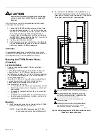
For systems requiring separate W1 and Y1 terminals for proper heat pump operation, refer to Fig. 18 and 19.
d
Replace existing sensor with C7089A Outdoor Sensor.
W8900B Terminal
Designations
Function
Existing Thermostat
Designations
(Standard)
Existing Thermostat
Designations
(Customer Specials)
1
PC8900A Control Panel
—
—
2
PC8900A Control Panel
—
—
3
PC8900A Control Panel
—
—
4
PC8900A Control Panel
—
—
AUX
a
Stage-3 heat control (strip heat)
W3
—
B
Heating, changeover valve
B
—
C
24 Vac transformer common
C
X,B
CO
2
Carbon dioxide monitor
—
—
E
Emergency heat relay
E
K
VNT
VNT relay
—
—
G
Fan relay
G
F
GND
Ground
—
—
L
System monitor
L
L
O
Cooling, changeover valve
O
R
R
24 Vac system transformer
R
V
S, S1
Remote Air Temperature Sensor
—
—
T, T1
Discharge Air Temperature Sensor
—
—
W2
b
Stage-2 heat control (compressor)
W2
H2,Y,R4
Y1/W1
c
Compressor contactor
—
RS
Y1/W1
c
Compressor contactor
Y
M
Y1/W1
c
Stage-1 cool control
Y1
C1,M
Y1/W1
c
Stage-1 heat control
W1
H1,R3
Y2
Stage-2 cool control
Y2
C2
None
Clogged filter switch or common connection
X
X1,X2,C
None
Defrost
—
P
None
HSII Control Panel
—
L,C,H
None
LEDs
—
A,A1,A2,Z,C,L
None
LO and HI speed fan relays
—
R1,R2
None
Momentary circuit, changeover
—
O
None
Outdoor thermistor
T
A
Out
d
External temperature readout, T relay
—
—