


RP-2002 Series Manual —
P/N 53039:E6 1/26/2017
93
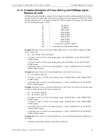
Calculating the System Current Draw
Power Supply Calculations
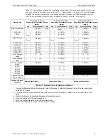
Table 5.3 contains three columns for calculating current draws.
For maximum output current avail-
able per circuit and per panel, refer to Section 1.2, “Specifications”, on page 14.
For each column,
calculate the current and enter the total (in amperes) in the bottom row. When finished, copy the
totals from Calculation Column 2 and Calculation Column 3 to Table 5.4 on page 94.
Device Type
Calculation Column 1
Primary, Non-Fire Alarm Current
(amps)
Calculation Column 2
Secondary, Fire Alarm Current
(amps)
Calculation Column 3
Secondary, Non-Fire Alarm Current
(amps)
Qty
X[current draw]=
Total
Qty
X [current draw] =
Total
Qty
X[current draw]=
Total
Main Circuit Board
1
X[0.095]=
0.095
1
X[0.221]
1, 2
=
0.221
1
X[0.095]=
0.095
N-CAC-5X
[ ]
X[0.001]=
[ ]
X[0.001]=
[ ]
X[0.001]=
4XTM
[ ]
(1 max.)
X[0.005]=
[ ]
X[0.011]1=
[ ]
X[0.005]=
ANN-SEC Card
[ ]
(1 max.)
X[0.003]=
[ ]
(1 max.)
X[0.003]=
[ ]
(1 max.)
X[0.003]=
N-ANN-80(C)
[ ]
X[0.037]=
[ ]
X[0.040]=
[ ]
X[0.015]=
N-ANN-I/O
[ ]
X[0.035]=
[ ]
X[0.200]=
[ ]
X[0.035]=
N-ANN-RLY
[ ]
X[0.015]=
[ ]
X[0.075]=
[ ]
X[0.015]=
N-ANN-(R)LED
[ ]
X[0.028]=
[ ]
X[0.068]=
[ ]
X[0.028]=
N-ANN-S/PG
[ ]
X[0.045]=
[ ]
X[0.045]=
[ ]
X[0.045]=
2-wire Detector
Heads
[ ]
X[ ]
3
=
[ ]
4
X[0.040]=
[ ]
4-wire Detector
Heads
[ ]
[ ]4
X[0.040]=
[ ]
Power Supervision
Relays
5
[ ]
X[0.025]=
[ ]
X[0.025]=
[ ]
X[0.025]=
NAC #1
[ ]
X[ ]=
NAC #2
[ ]
X[ ]=
NAC #3
NAC #4
Current Draw from
TB9 (nonalarm)
[ ]=
[ ]=
[ ]=
Sum each column
6
for totals
Primary Non-Alarm =
Secondary Alarm =
Secondary Non-Alarm =
Table 5.3 System Current Draw Calculations
1 If using the Reverse Polarity Alarm output, add 0.005 amps; if using the Reverse Polarity Trouble output, add
another 0.005 amps.
2 The current shown represents one zone (IDC) on the main circuit board in alarm. One zone consumes 0.040
amps.
3 Refer to the
Device Compatibility Document
for standby current.
4 Enter the number of IDCs used minus one.
5 Must use compatible listed Power Supervision Relay.
6 Total current draw listed above cannot exceed 7.2 amps
Summary of Contents for NOTIFIER RP-2002C
Page 158: ...Cut along dotted line ...