


2
PRODUCT IDENTIFICATION SYSTEM
C
-Electrical Motor
N
-Fail Safe Function (Non-Spring Return)
61
-24V Floating Control
75
-24V Modulating Control
05
-44 lb-in. (5 Nm)
10
-88 lb-in. (10 Nm)
A
-Standard Model
1
-No Feedback
2
-Voltage Feedback Signal
0
-No Internal Auxiliary Switches
2
-Two Internal Auxiliary Switches
XX-
System Controlled Numbers
C
N
75
10
A
2
0 XX
BASIC FEATURES
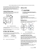
Fig. 1. Setting units and control elements
Legend for Fig. 1:
1) Universal shaft adapter
2) Mechanical end limits (manually adjustable)
3) Declutch button
4) Function selection switch
5) Removable access cover
6) Anti-rotation bracket
Contents of Package
The delivery package includes the actuator, parts 1 through 6
(see Fig. 1), plus two cable grommets and a spare cable
grommet.
RUN MODES
The function selection switch (see Fig. 2) can be used to place
the actuator into any one of two different modes:
• Service/Off; or
• the floating/2-position run mode (“Dir” for CCW-closing
dampers or “Rev” for CW-closing dampers).
• the modulating run modle.
Fig. 2. Function selection switch
Power-Off Behavior
If power is removed, the shaft adapter remains in position.
Service/Off
If the function selection switch is set to the “Service/Off” position,
then all rotary movement is cancelled, and all control signals are
ignored, thus allowing the actuator to be manually operated
safely.
Floating/2-Position Run Mode
Without Feedback Signal
If, however, the function selection switch has been set to one of
the two floating/2-position control settings - but the actuator has
not been wired for a feedback signal (see Fig. 12 and Fig. 13) -
then as soon as operating power is applied, the shaft adapter will
run according to the control signals applied.
With Feedback Signal
If the function selection switch has been set to one of the two
floating/2-position control settings - and if the actuator has been
wired for a feedback signal (see Fig. 12 and Fig. 13) - then as
soon as operating power is applied, the shaft adapter will likewise
run first completely counterclockwise and then completely
clockwise (see also section “Adaption”), after which it will run
according to the control signals applied.
Modulating Run Mode
If the function selection switch has been set to one of the four
modulating control settings - and if the actuator is wired
correspondingly (see Fig. 10) - then as soon as operating power
is applied, the shaft adapter will run first completely
counterclockwise and then completely clockwise (see also
section “Adaption”), after which it will run according to the control
signals applied.
63-6233T
CN0B-0545CH33 R0805
N05,N10 SERIES DAMPER ACTUATORS FOR MODULATING AND FLOATING CONTROL