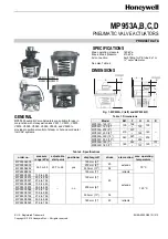

MP953A,B,C,D PNEUMATIC ACTUATORS
EN0B-0552GE51 R1210
2
FEATURES
Rolling diaphragm for long life and low hysteresis
Easily attached to valve assembly
May be installed after valve piping
Slide lock feature permits simple engagement to valve
stem
Models with positive-positioning relay available
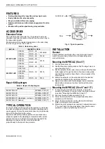
ACCESSORIES
Extension Yokes
The extension yoke (see also Fig. 7) provides for extra air
circulation and less conduction of heat from the valve body to
the pneumatic actuator.
Recommended if the medium temperature in the valve body
is in the range of from 150 to 220 °C.
Table 3. Extension yokes
part no.
applied to valves
V5049A DN
15…65
V5050A DN
15…80
PN 25/40
V5025A
DN 15…80
PN 25
V5016A DN
15…80
V5328A
V5329A
DN 40…80
PN 16
43161276-001
V5329C
DN 40…80
PN 6
V5011R,S
V5013R,E
V5328A
V5329A
DN 15…32
PN 16
43297431-001
V5329C
DN 15…32
PN 6
Repair Kit Diaphragm
Table 4. Repair kit diaphragms
part no.
model
R43312760-001
MP953A,C 125 (5")
R43161319-001
MP953A,C 200 (8")
R43161320-001
MP953A,C 330 (13")
R43180626-001 (diaphragm. a. sleeve
MP953B,D 180 (7")
R43161322-001 (sleeve)
MP953B,D 180 (7")
TYPICAL OPERATION
In a direct-acting (normally-open valve) system, an increase
in control air pressure will force the actuator diaphragm and
cup downward, forcing the valve stem down to proportionally
close off the flow through the valve.
Operators without the positive positioner have branch line
pressure applied to the diaphragm. Operators with positive
positioners have up to full main air pressure applied to the
diaphragm to ensure that the valve is positioned
proportionally to the branch line pressure.
control air
valve
stem
flow
Fig. 2. Typical operation
INSTALLATION
General
Ensure that the actuator has the correct size and travel to
match the valve body. Refer to the corresponding valve
product literature.
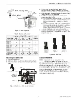
Mounting the MP953A,C (Size 5")
1.
Pull the valve stem up.
2.
Position the stem-locking slide so that the large hole is in
view (see also Fig. 3).
3.
Set the actuator on the valve bonnet. Ensure that the stem
button passes through the hole in the stem-locking slide
and that the actuator is down flush on the shoulder of the
valve bonnet.
4.
Rotate the actuator on the valve bonnet to the desired
position and tighten both actuator set screws.
5.
Apply air pressure until the diaphragm cup contacts the
stem button and secure the stem button with the stem-
locking slide.
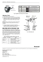
Mounting the MP953A,C (Size 8" and 13")
1.
If converting from smaller-size actuator, remove the
actuator by following, in reverse order, the steps outlined
in section "Mounting the MP953A,C (Size 5")".
2.
Remove the stem button (see also Fig. 5).
3.
Screw the stem button on the (single or double) stem
extension until it bottoms.
4.
Screw the stem extension on the stem until it bottoms
(flats or locking-pin hole provided).
5.
Rotate the stem extension as required to adjust dimension
"Y" as per Table 5 to the value listed, then lock the stem
extension in place by tightening the hex nut.