


2.
3.
4.
5.
6.
7.
See WARNING in this section. Sequentially loosen
fasteners securing base to frame.
Base pops
frame when fasteners disengage.
When tension is relieved, remove fasteners and base.
Install new base assembly.
Reinstall fasteners.
NOTE: Considerable force may be required before
the positioner begins to turn because of the
large O-ring that seals the Relay/positioner
to the Actuator cover.
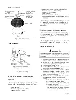
3. Remove feedback spring. Retain old spring for
Reassemble Actuator assembly by following 4. Install original feedback spring in diaphragm cup
procedure in Steps 1 and 2 in reverse order. when Relay/positioner is being replaced with an
Reinstall air lines and restore system to service. identical device.
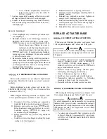
REPLACE ACTUATOR MAIN
SPRING
C, E DIRECT-ACTING ACTUATORS
Remove the main
on direct-acting Actuators
safely
by following the procedure in REMOVE ACTUATOR
COVER under
C, E DIRECT-ACTING
ACTUATORS in REPLACE MAIN DIAPHRAGM
section. This procedure relieves all internal spring force and
makes the spring fully accessible.
See PARTS for the proper replacement spring.
D, F REVERSE-ACTING ACTUATORS
Remove the main spring on reverse-acting Actuators
safely by following the procedure in
D, F
DIRECT-ACTING ACTUATORS in REPLACE MAIN
DIAPHRAGM section. This procedure relieves all internal
spring force and makes the spring fully accessible.
See PARTS for the proper replacement spring.
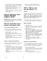
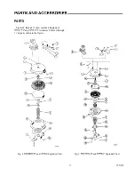
REPLACE GRADUTROL RELAY/
POSITIVE POSITIONER
E DIRECT-ACTING ACTUATORS
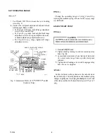
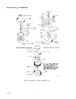
When using the following procedure, see Figure 8 for an
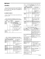
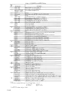
exploded diagram and Table
6
for parts.
To prevent damage to the
wrench force must only
1.
2.
Disconnect all air lines.
Unscrew Relay/positioner counterclockwise from
Actuator cover and remove.
5. When replacing Gradutrol Relay with a new-style
positive positioner, discard original spring and install
feedback spring with proper range from appropriate
retrofit kit. For part number, see POSITIONER
RETROFIT AND SPRING KITS in PARTS AND
ACCESSORIES.
6.
Position new O-ring in groove of Relay/positioner
base and install new Relay/positioner in Actuator
cover.
NOTE: Compress feedback spring as the Relay/
positioner is screwed in place. Check that
both ends of the feedback spring are located
in the spring cups, one in the Relay/
positioner and one cemented to the Actuator
diaphragm.
7. Tighten Relay/positioner only enough to seat large
of position and damage Actuator diaphragm and
feedback spring when unit is destroked.
8. Reinstall air lines and restore system to service.
9. Adjust range
only) and/or start point. See
MAINTENANCE.
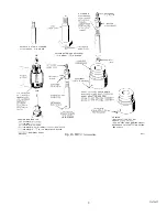
F REVERSE-ACTING ACTUATORS
When using the following procedure, see Figure 9 for an
exploded diagram and Table 7 for parts
Disconnect all air lines, including short tube from
Relay/positioner to side of Actuator cover.
Remove three screws that locate the Relay/positioner
bracket assembly on the Actuator cover.
Remove bracket assembly. Retain original bias and
feedback springs when Relay/positioner is being
replaced with an identical device,
When replacing Gradutrol Relay assembly with
style positive positioner assembly, discard original
bias and feedback springs and install springs with
proper range from appropriate retrofit kit. For part
number, see POSITIONER RETROFIT AND
SPRING KITS in PARTS AND ACCESSORIES.
75-5500