Honeywell ML7421A1032 Product Data Download Page 6

ML7421A,B  ELECTRIC  LINEAR  VALVE  ACTUATOR

63-2517-2

6

Output Signal Feedback (F)

An analog output signal (2 to 10 Vdc) that represents the
actual actuator stem position is available at Terminal F. It
can be used for remote indication of the stem position.
When the actuator stem is fully extended, the output signal
is 10 Vdc.

The output of the signal does not change when the action of
the actuator is reversed using W3 or  W4, which is set to
mA-position, see Direction of Action.

Actuator Override

The converter output signal override position can be used in
freeze protection or similar applications. it forces the
actuator into an end position, overriding the control signal.
To exercise this function, connect the 24 Vac common (or
T2) to either terminal O1 or O2.
connecting to terminal O1 fully extends the actuator stem.
connecting to O2 fully retracts the actuator stem.

The control signal is ignored when the override signal is
applied to terminal O1 or O2. this override can be achieved
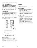
with a switch or relay, see Fig. 9.

Fig. 9. Connection for overriding control sigal to

drive actuator to specific position.

CHECKOUT

The ML7421 Electric Linear Valve Actuator can be checked
out either directly or using a controller.

1. Mount the actuator for the required application.
2. Check the valve position and make sure that 24 Vac is

correctly applied to the actuator.

3. Apply the control signal to the appropriate leadwires

to move the valve in the required direction.

4. If the actuator does not move, make sure the actuator

is properly installed.

5. If the actuator is correctly installed and does not run,

replace the actuator.

Direct Checkout

Controller Checkout

1. Adjust the setpoint of the controller to call for opening

or closing the valve. Observe the actuator.

2. If the valve is closed, it should begin to open.
3. If the valve remains closed, move the setpoint further

towards the open setting.

4. If the valve does not move, check for 24 Vac in the

actuator power input.

5. If 24 Vac is present and the actuator does not operate,

reverse the controller leadwires to determine if the
device is miswired.

6. If the wiring is correct, 24 Vac is present on the power

input  terminals, and the actuator does not run, replace
the actuator.

Direction of Action

The direction of the actuator action can be changed by
repositioning selector plug W3, which is factory set so that
the stem extends on increasing signal and retracts on
decreasing signal. When the actuator stem is fully extended
the output signal from feedback  (F) function is 2 Vdc.

Summary of Contents for ML7421A1032

Page 1: ... in heating ventilating and air conditioning HVAC applications 63 2517 2 FEATURES Quick and easy installation No separate linkage required 3 4 in 20 mm stroke on ML7421A 1 1 2 in 38 mm stroke on ML7421B No adjustments required Accurate valve positioning Selectable 0 2 to 10 Vdc 0 4 to 20 mA input signal Position feedback Force limiting end switches Manual operator Direct or reverse acting Synchron...

Page 2: ...ckout holes for 1 2 in and 3 4 in conduit standard on actuator case Actuator Material Cover ABS plastic Yoke and Base Diecast aluminium Weight 5 1 lb 2 3 kg Dimensions See Fig 1 Accessories 43191680 102 Dual Auxiliary Switch for ML7421A B for 24 Vac use only 43196000 101 High Temperature Kit Includes 1 4 in and 3 8 in stem extenders The kit increases the temperature range to 428 F 220 C 43196000 1...

Page 3: ...ator in in mm Valve Model Valve Size in in Close Off Rating psi kPa a 404 lbf 1800N V3350 V3351 2 1 2 63 434 V3360 V3361 3 45 310 V3450 V3451 4b 25 172 V3460 V3461 5b 16 110 6b 11 76 INSTALLATION When Installing this Product 1 Read these instructions carefully Failure to follow them could damage the product or cause a hazardous condition 2 Check the ratings given in the instructions and on the pro...

Page 4: ...rough 6 connect the power and control wires to the ML7421 Make sure that all wiring is correct 3 When wiring and checkout are complete replace the cover tighten the cover screws and replace the manual operator knob see Fig 7 4 Apply cover and control signals to the ML7421 Fig 4 ML7421 typical wiring diagram Fig 5 ML7421 wiring diagram using a 0 2 to 10Vdc output control e g T7759 with two transfor...

Page 5: ... the the manual operator knob so the manual operator automatically disengages on power resumption Auxiliary switches The 43191680 Dual Auxiliary Switch can be used on both the ML7421A and ML7421B Electric Linear Valve Actuators Switching points are adjustable over the full length of the actuator stroke for example the switch can be used to switch pumps or to provide remote indication of any stroke...

Page 6: ...an be checked out either directly or using a controller 1 Mount the actuator for the required application 2 Check the valve position and make sure that 24 Vac is correctly applied to the actuator 3 Apply the control signal to the appropriate leadwires to move the valve in the required direction 4 If the actuator does not move make sure the actuator is properly installed 5 If the actuator is correc...

Page 7: ...s or services please write or phone 1 Your local Home and Building Control Sales Office check white pages of your phone directory 2 Home and Building Control Customer Logistics Honeywell Inc 1885 Douglas Drive North Minneapolis Minnesota 55422 4386 612 951 1000 In Canada Honeywell Limited Honeywell Limitée 155 Gordon Baker Road North York Ontario M2H 3N7 International Sales and Service Offices in ...

Page 8: ...o 30 Harbour Road Wanchai HongKong Home and Building Control Honeywell Limited Honeywell Limitée 155 Gordon Baker Road North York Ontario M2H 3N7 Honeywell Latin American Region 480 Sawgrass Corporate Parkway Suite 200 Sunrise FL 33325 Home and Building Control Honeywell Inc Honeywell Plaza P O Box 524 Minneapolis MN 55408 0524 www honeywell com 63 2517 2 Printed in U S A 7 99 ...

Reviews: