Honeywell ML7421A Product Data Download Page 3

ML7421A,B ELECTRIC LINEAR VALVE ACTUATOR

63-2517—1

3

Table 1. Close-off Ratings in psi for ML7421A,B Electric Linear Valve Actuators and V5011, V5013 Valves.

Valve

Type

1/2 in.

3/4 in.

1 in.

1-1/4 in.

1-1/2 in.

2 in.

2-1/2 in.

3 in.

4 in.

a

5 in.

a

6 in.

a

V5011A

Flange

N/A

N/A

N/A

N/A

N/A

N/A

77

53

29

18

12

V5011B

Flange

N/A

N/A

N/A

N/A

N/A

N/A

N/A

N/A

29

18

12

V5011F

Screw

150

150

150

150

150

150

100

61

N/A

N/A

N/A

V5011G

Screw

150

150

150

150

150

150

100

61

N/A

N/A

N/A

V5013B

Flange

N/A

N/A

N/A

N/A

N/A

N/A

77

53

29

18

12

V5013C

Flange

N/A

N/A

N/A

N/A

N/A

N/A

77

53

29

18

12

V5013F

Screw

150

150

150

150

150

150

N/A

N/A

N/A

N/A

N/A

a

Only for use with ML7421B Actuator.

Fig. 1. Approximate dimensions of ML7421A,B Electric Linear Valve Actuator in in. (mm).

2-1/2 
(64)

2-1/2 
(64)

7 (178 ) X 7 (178)

7 (178 ) X 7 (178)

5-5/8
(142)

KNOCKOUTS
(2) 
7/8 (22)

9-3/8
(239)

10-3/8

(264)

14-1/4

(360)

8

(204)

11-7/8

(301)

12-3/4

(326)

16-7/8

(430)

ML7421A

ML7421B

M6744

YOKE DIAMETER 1-3/8 (35)

KNOCKOUTS
(2) 
7/8 (22)

YOKE DIAMETER 1-7/8 (48)

Table 2. Close-off Ratings in psi for ML7421A,B Electric

Linear Valve Actuators and V3350,1; V3361;

V3450,1; V3460,1 Valves.
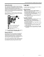
INSTALLATION

When Installing this Product...

1. Read instructions carefully. Failure to follow them could

damage the product or cause a hazardous condition.

2. Check ratings and description given in the

specifications to make sure the product is suitable for
your application.

3. Installer must be a trained, experienced service

technician.

4. After installation is complete, check out product

operation as provided in these instructions.
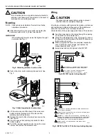
CAUTION

Disconnect power before installation to prevent
electrical shock or equipment damage.

Location

Install the actuator in a location that allows enough clearance
for mounting accessories and for servicing. See Fig. 1.

a

Represents maximum pressure difference between the
outlet and either of the two inlets.

b

Only for the use with ML7421B Actuator.

Close-Off   

Rating psi (kPa)

a

Valve Model

Valve Size in in.

404 lbf (1800N)

V3350, V3351,

2-1/2

63 (434)

V3460, V3461,

3

45 (310)

V3350, V3351,

4

b

25 (172)

V3450, V3451

5

b

16 (110)

6

b

11 (76)

Summary of Contents for ML7421A

Page 1: ...andard Honeywell valves in heating ventilating and air conditioning HVAC applications FEATURES Quick and easy installation No separate linkage required 3 4 in 20 mm stroke on ML7421A 1 1 2 in 38 mm stroke on ML7421B No adjustments required Accurate valve positioning Low power consumption High close off ratings Force limiting end switches Manual operator Synchronous motor Corrosion resistant design...

Page 2: ...to 10 Vdc or 0 to 135 ohm 3 4 20 95 ML7421A1024 0 to 10 Vdc 3 4 20 95 ML7421B1007 2 to 10 Vdc or 0 to 135 ohm 1 1 2 38 175 ML7421B1015 0 to 10 Vdc 1 1 2 38 175 Electrical Ratings Power Input 24 Vac 10 15 60 Hz Power Consumption 12 VA maximum at 24 Vac Stem Force 405 lbf 1800N Ambient Temperature Range 14 F to 122 F 10 C to 50 C Storage Temperature Range 40 F to 158 F 40 C to 70 C Humidity 5 to 95 ...

Page 3: ...IAMETER 1 3 8 35 KNOCKOUTS 2 7 8 22 YOKE DIAMETER 1 7 8 48 Table 2 Close off Ratings in psi for ML7421A B Electric Linear Valve Actuators and V3350 1 V3361 V3450 1 V3460 1 Valves INSTALLATION When Installing this Product 1 Read instructions carefully Failure to follow them could damage the product or cause a hazardous condition 2 Check ratings and description given in the specifications to make su...

Page 4: ...and regulations Voltage and frequency of the transformer used with the ML7421 must correspond with the characteristics of the power supply and those of the actuator A Feed the power and control wires through the opening on the bottom of the actuator case B Using the wiring diagrams in Fig 4 through 9 connect the power and control wires to the ML7421 Make sure that all wiring is correct C When wiri...

Page 5: ... OR EVEN ON ALL MODELS BECAUSE THEY ARE FOR THE OPTIONAL 220 OHM FEEDBACK POTENTIOMETER T Y G M6748 40 VA 24 VAC Fig 8 ML7421 wiring diagram using a 4 to 20 mA output control e g T775 with two transformers L1 HOT L2 1 1 2 2 WIRING STRIP T1 T2 O1 R1 W1 B1 O2 1 1 2 2 3 3 4 5 6 L1 HOT L2 1 ML7421 T775 WITH 4 TO 20 MA OUTPUT DUAL TRANSFORMERS SENSOR POWER SUPPLY PROVIDE DISCONNECT MEANS AND OVERLOAD P...

Page 6: ...event of power failure Turn off or disconnect the power supply before manually operating the ML7421 To operate push down on the manual operator knob and turn the knob counterclockwise to move the stem downward or turn the knob clockwise to move the stem upward When the actuator is returned to automatic control the manual operator knob unlocks automatically NOTE If the manual operator knob is not p...

Page 7: ...rs by reversing the signal from the controller WIRING STRIP T1 T2 O1 O2 R1 W1 B1 1 L1 HOT L2 OUTPUT ML7421A B 2 POWER SUPPLY PROVIDE DISCONNECT MEANS AND OVERLOAD PROTECTION AS REQUIRED 0 TO 10 OR 2 TO 10 VDC CONTROL SIGNAL DEPENDING ON ACTUATOR MODEL SEE OVERRIDE SECTION FOR DETAILS ON OVERRIDE OPERATION 1 2 3 3 M6751 1 SP3T OVERRIDE SWITCH CHECKOUT The ML7421 Electric Linear Valve Actuator can b...

Page 8: ...trol Honeywell Limited Honeywell Limitée 155 Gordon Baker Road North York Ontario M2H 2C9 Honeywell Latin American Division Miami Lakes Headquarters 14505 Commerce Way Suite 500 Miami Lakes FL 33016 Helping You Control Your World 63 2517 1 C H Rev 10 96 Printed in U S A Home and Building Control Honeywell Inc Honeywell Plaza P O Box 524 Minneapolis MN 55408 0524 Printed on recycled paper containin...

Reviews: