PRODUCT DATA
Copyright © 1996 Honeywell Inc. • All Rights Reserved
ML7284
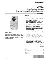
Non-Spring Return
Direct Coupled Damper Actuator
APPLICATION
The ML7284 Non-Spring Return Direct Coupled Damper
Actuator provides proportioning control of dampers in heating,
ventilation and air conditioning (HVAC) applications. The
motor accepts a current or a voltage signal from an electronic
controller to position a damper at any chosen point between
fully open and fully closed.
FEATURES
•
Mounts directly on 3/8 in. to 5/8 in. (10 to
17 mm) round and square and 3/4 in. (19 mm) round
damper shafts by using the appropriate insert. Most
models are shipped with 1/2 in. insert.
•
Provides 150 lb-in. (17 N•m) torque.
•
Magnetic coupling eliminates the need for mechanical
stops or limit switch adjustments by limiting stall
torque to 250 lb-in. (28.3 N•m) maximum.
•
95
°
stroke provides necessary compression of rubber/
neoprene gaskets commonly used on 90
°
low leakage
dampers.
•
Manual clutch allows for manual adjustment.
•
92 second synchronous timing can eliminate need for
feedback position indication in closed-loop tempera-
ture control applications.
•
Removable splined output hub permits premounting of
hub on damper shaft, providing installation flexibility.
•
Includes standard reverse/direct acting rotation switch,
on the outside cover.
•
Designed for both single-point and three-point
mounting, to allow installation flexibility.
•
Available with or without a time-out feature. Models
without the time-out feature are designed to be used
with intelligent building management system and/or
controller.
•
Standard models have two 8 mm by 12 mm long set
screws for securing the damper shaft. Actuator models
available for various shaft sizes that allow damper
shaft to operate centered inside the output hub.
•
Models available with 0 to 10 Vdc, 2 to 10 Vdc, and 4 to
20 mA inputs.
•
Models available with 2 to 10 Vdc feedback signal.
63-2504-2
Contents
Application .......................................................................... 1
Features ..............................................................................
1
Specifications ......................................................................
2
Ordering Information ...........................................................
2
Installation ........................................................................... 4
Operation ............................................................................
7
Checkout .............................................................................
8
Troubleshooting ..................................................................
8


