Honeywell ML6421 Product Data Download Page 5

ML6421, ML7421 NON-SPRING RETURN ELECTRIC LINEAR VALVE ACTUATORS

5

63-2515—4

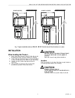
Fig. 5. ML6421 typical wiring diagram.

Fig. 6. ML7421 typical wiring diagram.

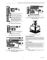
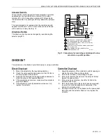
Fig. 7. ML7421 wiring using voltage input control and 

separate transformers.

Fig. 8. ML7421 wiring using voltage input control and a 

common transformer.

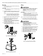
Fig. 9. Replacing actuator cover.

Auxiliary Potentiometers

The 43191679 Auxiliary Potentiometers can be used as feed-
back potentiometers and to provide remote indication of the 

valve position. See the Accessories section for part numbers. 

See Installation Instructions packed with the potentiometers 
for details.

Auxiliary Switches

The 43191680 Dual Auxiliary Switch can be used on both the 

ML6421 and ML7421 Electric Linear Valve Actuators. 

Switching points are adjustable over the full actuator stroke. 
For example, the switch can be used to switch pumps or to 

provide remote indication of any stroke position. See the 

Installation Instructions packed with the auxiliary switch for 
details.

IMPORTANT

Use the 43191680 Dual Auxiliary Switch only with 

24 Vac applications.

WIRING
STRIP

T1

T2

W

B

1

L1 
(HOT)

L2

W

R

W

B

T

Y

G

R

B

SPDT

ML6421A,B

2

3

POWER SUPPLY. PROVIDE DISCONNET MEANS AND 
OVERLOAD PROTECTION AS REQUIRED.

ALL WIRING BLOCKS HAVE THE SAME NUMBER 
OF TERMINALS (8), BUT THE ONLY TERMINALS 
THAT ARE ACTIVE ON THIS BLOCK ARE T1,W,AND B.

THE R-W-B AND T-Y-G TERMINALS ARE A SIX 
TERMINAL WIRING BLOCK SEPARATE FROM THE 
MAIN BLOCK. THEY DO NOT APPEAR ON ALL 
MODELS BECAUSE R-W-B ARE FOR A SINGLE 
FEEDBACK POTENTIOMETER AND T-Y-G ARE 
FOR A SECOND FEEDBACK POTENTIOMETER 
(BOTH POTENTIOMETERS ARE 220 OHMS). THE 
REQUIRED WIRING BLOCKS ARE PART OF THE 
POTENTIOMETER ACCESSORY KITS.

1

2

3

CONTROLLER

M17433

WIRING

STRIP

T1

+

T2

O1

O2

1

L1

L2

+

OUTPUT

2

POWER SUPPLY. PROVIDE DISCONNECT MEANS 
AND OVERLOAD PROTECTION AS REQUIRED.

0 TO 10 OR 2 TO 10 VDC CONTROL SIGNAL 
(DEPENDING ON ACTUATOR MODEL).

1

2

M17434A

ML7421

L1

L2

1

1

1

1

2

2

3

3

4

5

6

L1

L2

1

T775 (WITH 2 TO  10 VDC OUTPUT)

DUAL
TRANSFORMERS

SENSOR

POWER SUPPLY.  PROVIDE DISCONNECT MEANS 
AND OVERLOAD PROTECTION AS REQUIRED.

M17435A

WIRING

STRIP

T1

+

T2

O1

O2

ML7421

L1 
(HOT)

L2

1

1

1

1

2

2

3

3

4

5

6

T775 (WITH 2 TO 10 VDC OUTPUT)

SINGLE
TRANSFORMER

SENSOR

POWER SUPPLY.  PROVIDE DISCONNECT MEANS 
AND OVERLOAD PROTECTION AS REQUIRED.

M17436A

40 VA, 24 VAC

WIRING

STRIP

T1

+

T2

O1

O2

ML7421

M17464

Summary of Contents for ML6421

Page 1: ...tput of 0 to 10 Vdc or 2 to 10 Vdc These actuators operate standard Honeywell valves in HVAC applications An internal selector plug can be used to reverse the direction of action FEATURES Quick and easy installation No separate linkage required 3 4 in 20 mm stroke on ML6421A and ML7421A 1 1 2 in 38 mm stroke on ML6421B and ML7421B No adjustments required Accurate valve positioning Low power consum...

Page 2: ...nge 40 F to 158 F 40 C to 70 C Humidity Range 5 to 95 percent relative humidity noncondensing Approvals Canadian Standards Association Listed Underwriter s Laboratories Inc UL94 5V Flame Retardant file E181716 Meets CE requirements Protection Standard IP54 Accessories 43191679 101 Single Auxiliary Potentiometer for ML6421A 43191679 102 Single Auxiliary Potentiometer for ML6421B 43191679 103 Dual A...

Page 3: ...uct operation as provided in these instructions CAUTION Electrical Shock or Equipment Damage Hazard Can shock individuals or short equipment circuitry Disconnect power supply before installation Location Install the actuator in a location that allows enough clearance for mounting accessories and for servicing CAUTION Equipment Damage Hazard Can damage actuator due to condensation or a valve gland ...

Page 4: ...emoving actuator cover Wiring CAUTION Electrical Shock or Equipment Damage Hazard Can shock individuals or short equipment circuitry Disconnect power supply before installation IMPORTANT 1 All wiring must comply with local electrical codes ordinances and regulations 2 Voltage and frequency of the transformer used with the actuator must correspond with the characteristics of the power supply and th...

Page 5: ...ons WIRING STRIP T1 T2 W B 1 L1 HOT L2 W R W B T Y G R B SPDT ML6421A B 2 3 POWER SUPPLY PROVIDE DISCONNET MEANS AND OVERLOAD PROTECTION AS REQUIRED ALL WIRING BLOCKS HAVE THE SAME NUMBER OF TERMINALS 8 BUT THE ONLY TERMINALS THAT ARE ACTIVE ON THIS BLOCK ARE T1 W AND B THE R W B AND T Y G TERMINALS ARE A SIX TERMINAL WIRING BLOCK SEPARATE FROM THE MAIN BLOCK THEY DO NOT APPEAR ON ALL MODELS BECAU...

Page 6: ...ase the spindle one turn by turning the manual operator knob This will ensure automatic disengagement of the manual operator upon power resumption NOTE If the manual operator knob is not pushed in while turned it will rotate only a short distance before disengaging without power resumption Fig 10 Manual operator knob ML7421 Signal Input Failure Using selector plug W1 the actuator can be set to run...

Page 7: ...e leadwires to move the valve in the required direction 4 If the actuator does not move make sure the actuator is properly installed 5 If the actuator is correctly installed and does not run replace the actuator Controller Checkout 1 Adjust the setpoint of the controller to call for opening or closing the valve Observe the actuator 2 If the valve is closed it should begin to open 3 If the valve re...

Page 8: ...al Honeywell Europe S A Honeywell Latin American Honeywell Honeywell Limited Honeywell Limitée Control Products 3 Avenue du Bourget Region 1985 Douglas Drive North 35 Dynamic Drive Honeywell Building 1140 Brussels 480 Sawgrass Corporate Parkway Golden Valley MN 55422 Scarborough Ontario 17 Changi Business Park Central 1 Belgium Suite 200 M1V 4Z9 Singapore 486073 Sunrise FL 33325 ...

Reviews: