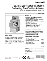


ML4105, ML4115, ML8105, ML8115 FAST-ACTING, TWO-POSITION ACTUATORS
63-2540—9
6
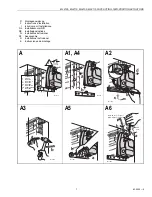
OPERATION
The ML4105, ML4115, ML8105, and ML8115 DCA are
designed for use in Smoke Control Systems. If power fails, the
actuator spring returns to the 0° position. The actuator mounts
flush with the damper box. The actuator drives from 0° to 95°
and spring returns back to 0°.
IMPORTANT
A break in power of less than two seconds can cause
the actuator to spring-return 5 degrees or less and
remain in place until a break in power of longer
duration.
The actuators are operated by an spst two-position controller.
When using an spst two-position controller, the actuator drives
to the damper fully open position when controller contact
makes and spring returns to the damper fully closed position
when controller contact breaks. The actuator drops to holding
power level on detection of stall, independent of hub position.
Cycling
The actuator and the internal spring are designed so that no
special cycling during long-term holding is required.
Honeywell recommends following all local, state, and national
codes for periodic testing of the entire smoke control system.
Refer to National Fire Protection Association (NFPA) National
Fire Codes
®
: NFPA90A, NFPA92A, and NFPA92B for your
application.
Temperature Indicator
The temperature indicator, located on the cover of the
actuator, provides evidence that the ambient temperature has
exceeded 200°F (93°C). This is an indication that something
in the building has caused temperatures to rise well above the
long-term actuator operation temperature. While the actuator
is capable of operating at 350°F (176°C) for extended periods
of time, this indicator provides a visual signal that the actuator
has been exposed to high temperatures for an undetermined
period of time. The indicator provides a visual indication to fire
authorities regarding the extent of damage after an event in
the building.
IMPORTANT
If the indicator turns black, replace the actuator.
NOTE: The actuator is designed to operate for 30 minutes
during a one-time excursion to 350°F (176°C).
CHECKOUT
ML4105A,B and ML4115A,B (120 Vac model)
1.
Verify that the indicator has not turned black (see
Temperature Indicator section).
2.
Check damper position.
3.
Connect 120 Vac to the black and white leadwires to
drive the damper to the open position. The actuator
should drive the damper.
4.
If the actuator does not run, remove power for at least
two seconds.
5.
If the actuator spring returns, allow it to close entirely,
then return to step 3.
6.
If the actuator does not spring return, verify that the
actuator is properly installed. See Installation section.
7. I
f the actuator is correctly installed but neither runs nor
spring returns, replace the actuator.
ML4105C,D and ML4115C,D (230 Vac model)
1.
Verify that the indicator has not turned black (see
Temperature Indicator section).
2.
Check damper position.
3.
Connect 230 Vac to the blue and brown leadwires to
drive the damper to the open position. The actuator
should drive the damper.
4.
If the actuator does not run, remove power for at least
two seconds.
5.
If the actuator spring returns, allow it to close entirely,
then return to step 3.
6.
If the actuator does not spring return, verify that the
actuator is properly installed. See Installation section.
7. I
f the actuator is correctly installed but neither runs nor
spring returns, replace the actuator.
ML8105 and ML8115 (24 Vac model)
1.
Verify that the indicator has not turned black (see
Temperature Indicator section).
2.
Check damper position.
3.
Connect 24 Vac to the red and black leadwires to drive
the damper to the open position. The actuator should
drive the damper.
4.
If the actuator does not run, remove power for at least
two seconds.
5.
If the actuator spring returns, allow it to close entirely,
then return to step 3.
6.
If the actuator does not spring return, verify that the
actuator is properly installed. See Installation section.
7.
If the actuator is correctly installed but neither runs nor
spring returns, replace the actuator.