e-4
Compact Unit Heater
Fuel Conversion Manual
section 2 Fuel conversion insTrucTions
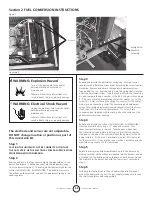
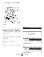
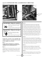
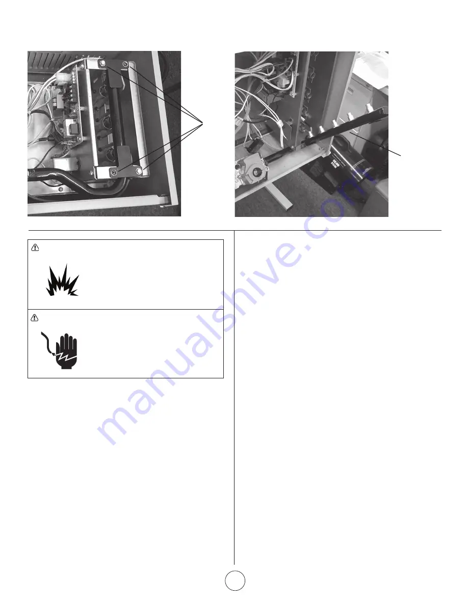
Figure 1
WarninG: explosion Hazard
Turn off the gas supply to the heater
before performing any service or
maintenance.
Failure to follow these instructions will
result in death, injury or property damage.
WarninG: electrical shock Hazard
Unplug the electrical cord from the outlet
before performing any service
maintenance.
Failure to follow these instructions will
result in death, injury or property damage.
step 1
cauTion THe uniT MusT noT Be connecTeD To eiTHer
THe Gas suPPlY or THe elecTrical PoWer suPPlY, BeFore
ProceeDinG WiTH conversion.
step 2
Remove and retain the four screws holding the manifold on to the
burner box (Figure 1). Rotate the valve/ manifold assembly, away
from the burners (Figure 2). The valve/manifold assembly holds the
orifices (3-HSU/MHU50, 5-HSU/MHU80. This will allow access to
the orifices on the manifold, and also the adjustment spring in the
valve/regulator.
step 3
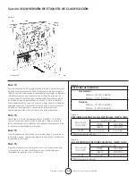
Remove and discard the adjustment spring cap ② from gas valve/
regulator with a flat blade screw driver by turning the screw counter-
clockwise. Remove and discard the regulator adjustment screw
found under the cap. Remove and discard the spring that is located
under the adjustment screw. Take the spring kit from the conversion
kit, and compare the part number of the kit to the parts list on page
3. If it does not match, immediately contact Mr. Heater, Inc. for the
correct kit. After confirming the spring kit is correct for the heater
model you are converting, install the new spring and adjustment
screw. Turn spring adjustment screw clockwise (in) until the screw
stops, then turn it counter-clockwise (back) 1 ½ turns. Place
conversion label supplied with the spring kit on the valve near the
adjustment screw cover opening.
step 4
Remove and discard the orifices (3-HSU/MHU50, 5-HSU/MHU80)
from the manifold with using a ½ “ open end wrench. Turn
them counter-clockwise to remove. Take the new orifices from
the conversion kit and before installing, confirm that the number
stamped on the side of the orifice matches the number for the kit
being installed. If it does not, immediately contact Mr. Heater, Inc.
for the correct kit. If they are the correct orifices, install them in the
manifold using caution not to cross thread.
step 5
Rotate the valve/ manifold assembly back up into the burner box,
making sure that all the orifices are indexed into the burners and are
not caught on the locating ring on the back of each burner. Secure
the manifold to the burner box with the four screws ② removed in
step 2.
step 6
Following the instructions in the unit heaters operations manual
mount the heater and connect the gas supply (making sure to leak
check all connections with soapy water).
The electrode and sensor are not adjustable.
Do noT change location or position as part of
this conversion kit.
Honeywell
4 Screws
Rotate Valve/
Manifold
Assembly

