Honeywell L4188 Product Handbook Download Page 2

EN2R-9005 0406R3-NE

2

DESCRIPTION OF DEVICE FUNCTIONS 

Aquastats thermostats

Honeywell manufactures a coprehensive range of water 
temperature thermostats (trade name Aquastat) for controlling 
and limiting boiler water temperature in hydronic heating 
systems.
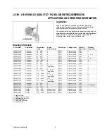
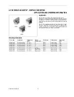
These sensitive, fast response devices are available in either 
direct, panel or surface mount versions.
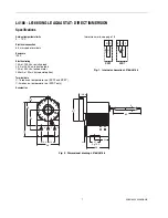
Sensing element

The liquid filled sensing element, including well or sensor 
assembly, responds to temperature changes of water in a 
heating system.
The sensor element has a diaphragm type power head 
connected to a tube type capsule, through a small bore 
capillary.
Expansion of the liquid, which completely fills the sensing 
element, is the means of motion of the diaphragm.
The sensor assembly, used on the surface mounted aquastat, 
envelopes the sensing capsule by means of an aluminium 
heat shield for better heat conduction, an insulator of 
glasswool and a mounting bracket.

Control mechanism

The control mechanism is mounted into the thermoplastic 
housing. The mechanism transfers the motion of the 
diaphragm to a snap action switch (Micro Switch) and also 
provides the facility to adjust the temperature level on which 
the Micro Switch has to operate.
The mechasnism consists of a two piece lever with calibration 
screw, a plastic actuator for the switch, a cam and shaft for the 
set-point adjustment, a loading spring for cam and levers and 
a pad with pushplate to transfer the diaphragm motion to the 
lever.

Knob with scale and index

The plastic knob with scale and index enables the user to 
adjust the Aquastat on a selected temperature setting within 
its range. The knob fits on the cam and stays on it due to the 
force of the spring on the nave of the knob.
This spring force enables the installer to pull the knob from the 
cam without the use of tools.
The hole in the knob and the shaft of the cam are provided 
with a flat side which allows mounting of the knob only in one 
position in order to maintain the calibration.
The plastic index will be fastened by means of two M4 thread 
forming screws on the housing.

Micro Switch

The Micro Switch mechanism is also mounted into the plastic 
housing. the mechanism consists of a snap action spring type 
PL with contacts and a moveable or a fixed and a stationary 
contact bracket.

The Micro Switch mechanism is intended to control electrically 
a burner, a relay, etc. in dependency of the temperature 
changes in a heating system.
On choice the Micro Switch mechanism can be delivered with 
the following contact arrangements:

S

ingle 

P

ole 

S

ingle 

T

hrow,

C-1 breaks on temperature rise

S

ingle 

P

ole 

D

ouble 

T

hrow,

C-1 breaks on temperature rise.
C-2 makes on temperature rise.

The contacts are connected to 6.3 mm terminals which are 
extending from the outside of the Aquastat housing.

Cover and conduit entries

The housing(s) of the Aquastat can be provided with conduit 
boxes which are provided with holes to fit Pg 13.5 conduits.
To obtain easy wiring possibilities these boxes can be 
mounted or disconnect without the use of tools (hook in 
approach).
The conduit box is locked with the front cover, which is 
fastened by means of an M3 thread forming screw. Also the 
top cover is locked by the front cover.

Set-point stops

On request, the Aquastat can be delivered with a high and low 
limit stop. The purpose of these stops is to provide the user 
with the facility to choose a maximum and/or minimum setting 
on the scale.
The stop is situated on the rear side of the setting knob. 
Adjustment is only possible after removal of the knob.

Manual or tool reset

On request, the Aquastat can be delivered with a manual reset 
or a tool reset feature.
The tool reset feature is covered by the front cover. 
Operating of the reset button is only possible after removal of 
the front cover.
The manual reset button potrudes the front cover of the 
Aquastat and resetting can be done without the use of a tool.

Adjustable differential

On request, it is possible to deliver the Aquastat with an 
adjustable switch differential.
The adjustable switch differential feature consists of a plastic 
adjusting dial with pointer, which is connected to a moveable 
contact. 
Turning of the dial changes the contact gap of the Micro 
Switch and thus the differential.
The dial is situated under the front cover or behind the panel.
Adjustable differential feature is only applicable on 

controllers


and 

recycling limit controls

Summary of Contents for L4188

Page 1: ...ed heating systems and systems for hot water supply mainly domestic use Contents General page Description of device functions 2 Description 3 Overview selection guide 4 Features 5 Aquastat series L4188 L6188 6 L4189 L6189 8 L6190 10 L4191 L6191 12 L6188A 2044 Tradeline 14 Performance 16 Construction 17 Various Accessories and spare parts 18 Quality assurance statement 20 Standards and approvals 20...

Page 2: ...e Micro Switch mechanism is also mounted into the plastic housing the mechanism consists of a snap action spring type PL with contacts and a moveable or a fixed and a stationary contact bracket The Micro Switch mechanism is intended to control electrically a burner a relay etc in dependency of the temperature changes in a heating system On choice the Micro Switch mechanism can be delivered with th...

Page 3: ...The Aquastat mechanism is directly attached to this sensor The L41 L61 series aquastats are primarily designed for application on water filled heating systems and systems for hot water supply mainly domestic use The L41 L61 series aquastats can be divided in the following main types Controller Controls the water temperature in accordance with the setting of an external knob TÜV type TR Recycling l...

Page 4: ...tandard sensing element Direct mount immersion L4188A B C 25 95 C 40 110 C 70 140 C L6188A B C 25 95 C 40 110 C 70 140 C L4191A B and L6191A B 25 95 C 50 95 C 40 110 C 70 140 C Panel mount immersion L4189A B C 25 95 C 40 110 C 110 230 F L6189A B C 25 95 C 40 110 C 70 140 C 110 230 F Surface mount with mounting strap L6190A B C 25 95 C Replacement aquastat immersion L6188A 2044 40 110 C ...

Page 5: ...l panel Cable entry in the conduit box is suitable for Pg 13 5 conduit or is provided with a plastic grommet at choice The high and low setpoint stops are field adjustabe with steps of 2 5 C Capillary available in 350 mm optional 1000 mm standard 1500 mm optional and 2000 mm optional length Surface mounted Aquastat can be mounted on cylinders of 300 460 mm diameter as well on pipes from 40 150 mm ...

Page 6: ...023 Controller 40 110 C 4 SPST External knob 5 L4188A 2031 Controller 25 95 C 4 SPST External knob 5 L4188B 2005 Controller 40 110 C 4 SPST Internal screw 4 5 L4188B 2013 Controller 25 95 C 4 SPST Internal screw 4 5 L6188A 2002 Controller 25 95 C 4 10 adjustable SPDT External knob 6 L6188A 2010 Controller 40 110 C 4 10 adjustable SPDT External knob 6 L6188A 2028 Controller 25 95 C 4 10 adjustable ...

Page 7: ...sistive load 2 5 A at 250 Vac inductive load 15 A at 250 Vac locked motor 250 mA at 30 mVdc special option Terminal data C 1 breaks on temperature rise SPDT and SPST C 2 makes on temperature rise SPDT only Accessories Immersion wells see page 18 Fig 1 Internal schematics L4188 L6188 Fig 2 Dimensional drawing L4188 L6188 C 1 C SPDT SPST 1 2 47 1 21 Pg 13 5 C 1 2 5 11 5 72 48 32 9 14 4 14 48 11 5 14...

Page 8: ...097 Controller 25 95 C 4 SPST External knob 1000 5 L4189A 2105 Controller 25 95 C 4 SPST External knob 350 1 6 L4189B 2012 Controller 100 230 F 4 SPST Internal screw 1000 3 L6189A 2001 Controller 25 95 C 8 SPDT External knob 1500 2 L6189A 2019 Controller 25 95 C 4 SPDT External knob 1500 L6189A 2043 Controller 40 110 C 4 10 adjustable SPDT External knob 1500 L6189A 2068 Controller 25 95 C 4 SPDT E...

Page 9: ... at 250 Vac locked motor 250 mA at 30 mVdc special option Terminal data C 1 breaks on temperature rise SPDT and SPST C 2 makes on temperature rise SPDT only Capilliary length 350 mm 1000 mm 1500 mm and 2000 mm Accessories Immersion wells see page 18 Fig 3 Internal schematics L4189 L6189 Fig 4 Dimensional drawing L4189 L6189 C 1 C SPDT SPST 1 2 Panel C 1 2 Mounting hole 2 for M4x20 tread forming sc...

Page 10: ...not required The required temperature control point is easily set using a screw driver Ordering information O S number Application Temperature range Switch differential K Switch type Setting means Strap length mm L6190A 2016 Surface mounting 25 95 C 8 SPDT External knob 250 L6190B 2006 Surface mounting 25 95 C 8 SPDT External setting 2000 L6190B 2014 Surface mounting 25 95 C 12 SPDT External setti...

Page 11: ... 6 3 mm spade terminals or screw terminals Enclosure IP40 Electrical rating 10 A at 250 Vac resistive load 2 5 A at 250 Vac inductive load 15 A at 250 Vac locked motor Terminal data C 1 breaks and C 2 makes on temperature rise Capilliary length 55 mm Fig 5 Internal schematic L6190 Fig 6 Dimensional drawing L6190 C SPDT 1 2 6 72 6 26 5 100 12 51 30 92 9 24 48 24 ...

Page 12: ...ithout knob and index O S number Application Temperature range Switch differential K Switch type Setting means Remarks see notes L4191A 2002 Controller 25 95 C 4 SPST External knob 9 Limiter 25 95 C 4 SPST Internal screw 9 L4191A 2010 Controller 25 95 C 4 SPST External knob 7 9 10 Limiter 25 95 C 4 SPST Internal screw 9 L4191B 2018 Controller 70 140 C 4 SPST External knob 6 Limiter 70 140 C Manual...

Page 13: ... A at 250 Vac inductive load 15 A at 250 Vac locked motor 250 mA at 30 mVdc special option Terminal data C 1 breaks on temperature rise C 2 makes on temperature rise Accessories Immersion wells see page 18 Fig 7 Internal schematics Fig 8 Dimensional drawing L4191 L6191 C 1 C SPST Control 1 2 C 1 SPST Limit SPST Control SPDT Limit C 1 C 1 2 SPDT Control SPDT Limit C 1 C 1 2 SPDT Control C 1 2 SPDT ...

Page 14: ...8A 2044 Aquatat thermostat to field replace Honeywell Aquastat thermostats as well as many competitive devices using the existing well No draining of the system is needed Ideal for service organisations to stock since only one Aquastat is needed for most calls If a new immersion well is needed order separately Ordering information L6188A 2044 1 High limit stop at 95 C low limit stop at 50 C O S nu...

Page 15: ...95 C Ambient temperature limits 0 70 C Electrical connection 6 3 mm spade terninals Enclosure IP40 Electrical rating 10 A at 250 Vac resistive load 2 5 A at 250 Vac inductive load 15 A at 250 Vac locked motor Terminal data C 1 breaks on temperature rise C 2 makes on temperature rise Accessories Immersion wells see page 18 Fig 9 Internal schematic Fig 10 Dimensional drawing L6188A 2044 C 1 2 SPDT 4...

Page 16: ...e maximum reset differential might be 30 C NOTE The differential thermal is dependant on the rate of change of the temperature in the heating system The given differential datas are valid for a rate of 1 C per minute Ambient temperature error Example An ambient error ratio of 1 6 means that an ambient change of 6 C will cause a setpoint shift of the Aquastat of 1 C Time constant With well τ 30 s f...

Page 17: ...ts A thermoplastic conduit box with a cable entry A thermoplastic front cover to protect against touching of live parts A thermoplastic top cover for covering of units with internal setting An adjustable dial for the Micro Switch differential if applicable Dual direct mounted Aquastat needs the following extra parts Two single thermoplastic conduit boxes a right and a left one with cable entry A d...

Page 18: ...imum insertion length including thread 170 mm Suitable for Ø 5 mm sensor 45 900 409 006 100 Description Ordernumber Packing qty pcs Spud thread 1 2 BSPT Maximum insertion length including thread 105 mm Suitable for two Ø 5 mm sensors 45 900 409 007 20 Spud thread 1 2 BSPT Maximum insertion length including thread 105 mm Suitable for two Ø 5 mm sensors when used with spring Without spring suitable ...

Page 19: ...70 140 C 45 002 823 002 25 95 C 45 002 823 003 40 110 C 95 C 45 002 823 004 70 140 C 95 C 45 002 823 005 40 110 C 50 C 95 C 45 002 823 006 25 95 C 82 C 45 002 823 007 40 110 C 100 C 45 002 823 008 25 95 C 60 C 45 002 823 010 70 140 C 95 C 45 002 823 011 25 95 C 60 C 80 C 45 002 823 013 1 7 40 110 C 85 C 45 002 823 014 50 95 C 82 C 45 002 823 015 40 110 C 82 C 45 002 823 017 25 95 C 40 C 80 C 45 00...

Page 20: ... department using their own equipment All inspections incoming and assembly are performed by trained personel and according inspection procedures STANDARDS AND APPROVALS Standards The L41 L61 series Aquastats have been designed according the Low Voltage Directive 73 23 EEC This Low Voltage Directive is covered by approvals in Denmark Finland Norway Sweden and Switserland EMC Directive 89 336 EEC T...

Page 21: ...al reset Capillary length Fig 11 Model number chart L 4 1 X A 9999 X Ordering Specification number Specification number A Single knob setting Dual automatic reset limiter B Single internal setting screw Dual manual reset limiter C Single manual reset 88 Single aquastat direct immersion 89 Single aquastat panel mounting 90 Single aquastat surface mounting 91 Dual aquastat direct mounting 92 Triple ...

Page 22: ...9005 0406R3 NE 22 Home and Building Control Combustion Control Center Europe Honeywell BV Phileas Foggstraat 7 7821 AJ Emmen The Netherlands Tel 31 591 695911 Fax 31 591 695200 http europe hbc honeywell com ...

Reviews: