


HONEYWELL CONFIDENTIAL
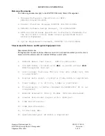
Preliminary UUT Set UP:
The Following Steps Must Be Preformed Before Power Is Applied To UUT.
Transmitter Final Board: (200-10256-0030)
b.
Adjust R1 fully counter clockwise (CCW)
c.
Adjust C44, C45 and C27 to mid range.
Transmitter Driver Board: (200-10252-0030)
a.
Adjust R3 fully counter clockwise (CCW)
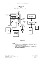
Test Equipment Set Up:
See Figure 1
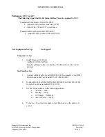
Computer Set Up:
1.
Install Diagnostic Software
( KPN 222-30128-XXXX )
Drag Kxp_Diag.exe file onto desktop. Double-click icon to activate
program.
Test Panel Set Up:
1.
Connect a RS232 cable from COMM Port of the computer to the RS232
DIAG input on the Test Panel (KPN 071-00224-0020).
2.
Connect Bench Test Cable (KPN 200-10336-0050 or 200-10336-0120)
from the Test Panel to the KXP2290 (UUT).
3.
Set Test Panel switches in the following positions:
a.
Air/Gnd = “OFF”
b.
Standby = “OUT”
c.
UUT Strap = “XPDR #1”
d.
Aircraft Power = “OFF”
4.
Connect a +28 volt power supply to Test Panel, be sure the polarity is
correct.
Honeywell International Inc.
001-05117-0010
KXP2290 Diversity Mode S Transponder
Revision -
Alignment Procedure
5 of 11
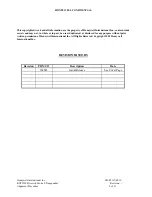
Summary of Contents for KXP2290
Page 1: ......