GB-2
D
GB
F
NL
I
E
Installation
CAUTION
Please observe the following to ensure that the
DL..K is not damaged during installation and op-
eration:
– Dropping the device can cause permanent dam-
age. In this event, replace the entire device and
associated modules before use.
– Condensation must not be allowed to get into
the housing (if possible, install pipework with an
ascending gradient). Otherwise, there is a risk of
icing of condensation at subzero temperatures,
the switching point shifting or corrosion in the
device which can lead to malfunctions.
– In the case of an uneven mounting surface,
secure the pressure switch to the mounting plate
or air duct with only two screws on the same
side in order to avoid subjecting the pressure
switch to mechanical stress.
– Protect the connections against dirt or moisture
in the medium to be measured or the surround-
ing air. If necessary, install a filter.
– When using silicone tubes, only use silicone
tubes which have been sufficiently cured. Va-
pours containing silicone can adversely affect
the functioning of electrical contacts.
– In case of highly fluctuating pressures, install a
damping nozzle.
▷
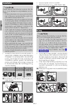
Installation in the vertical or horizontal position, or
upside down, preferably with vertical diaphragm.
If installed in a vertical position, the switching
point p
S
will correspond to the scale value SK.
If installed in another position, the switching
point p
S
will change and no longer correspond
to the set scale value SK. Switching point p
S
must be checked.
p
s
= SK
SK + 13 Pa
[+ 0.052 "WC]
SK - 13 Pa
[- 0.052 "WC]
1
Install the DL using screws, a securing clip or an
angle bracket.
66
4,4
(0.14")
ø 6,1
(ø 0.24")
(2.6")
▷
Tube connection: Ø 6 mm (0.236").
▷
Max. inlet presure p
max
= 5000 Pa (20 "WC).
Wiring
CAUTION
Please observe the following to ensure that the
DL..K is not damaged during operation:
– If the DL..G (DL..TG) has switched a volt-
age > 24 V (> 30 V) and a current > 0.1 A at
cos φ = 1 or > 0.05 A at cos φ = 0.6 once,
the gold plating on the contacts will have been
burnt through. It can then only be operated at
this power rating or higher power rating.
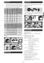
– Note the switching capacity, see page 3
▷
In the case of high humidity, we recommend
using a pressure switch with gold contact due to
its higher resistance to corrosion. Closed-circuit
current monitoring is recommended under dif-
ficult operating conditions.
▷
In the case of low switching capacities, such as
24 V, 8 mA, for example, we recommend us-
ing an RC module (22 Ω, 1 μF) in air containing
silicone or oil.
1
Disconnect the system from the electrical power
supply.
M16 x 1,5:
∅
4 – 10 mm
COM
3
NC
1
NO
2
NO
2
NC
1
COM
3
L1(+)
5
4
3
2


