GB-5
D
GB
F
NL
I
E
Adjustment
▷
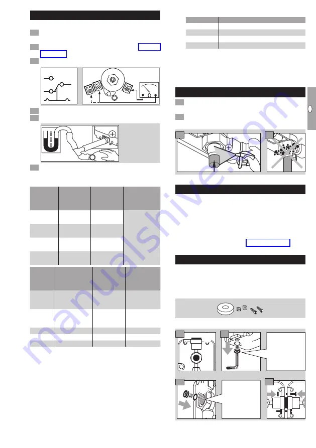
The switching point is adjustable via hand wheel.
1
Disconnect the system from the electrical power
supply.
Detach the housing cover, see page 7 (Tech-
Connect an ohmmeter.
NO
2
NC
1
COM
3
COM
3
NC
1
NO
2
0
1 cm = 1 mbar
4
Set the switching point using the hand wheel.
5
Connect a pressure gauge.
NO
2
NC
1
COM
3
COM
3
NC
1
NO
2
0
1 cm = 1 mbar
6
Apply pressure. In doing so, monitor the switch-
ing point on the ohmmeter and the pressure
gauge.
Type
Adjusting
range*
[mbar]
Reset
pressure**
[mbar]
Max. inlet
pressure
p
max.
[mbar]
DG 10H,
DG 10N
1 – 10
0.4 – 1
600
DG 50H,
DG 50N
2.5 – 50
1 – 2
DG 150H,
DG 150N
30 – 150
2 – 12
DG 500H,
DG 500N
100 – 500
5 – 18
Type
Adjusting
range*
[mbar]
Switching
differential***
[mbar]
Max. inlet
pressure
p
max.
[mbar]
DG 1,5I
-1.5 to -0,5
and
+0.5 to +3
0.2 – 0.5
±100
DG 12I
-12 to -1
and
+1 to +7
0.5 – 1
±100
DG 18I
-2 to -18
0.5 – 1.5
±100
DG 120I -10 to -120
4 – 11
±600
DG 450I -80 to -450
10 – 30
±600
*
Adjusting tolerance = ± 15% of the scale value.
** Difference between switching pressure and pos-
sible reset.
*** Mean switching differential at min. and max. set-
ting.
▷
Deviation from the switching point during testing
pursuant to EN 1854:
Gas pressure switches: ± 15%.
Air pressure switches:
Deviation
DG..H, ..N, ..I
± 15%
DG 1,5I
± 15% or ± 0.4 mbar
DG 12I
± 15% or ± 0.5 mbar
DG 18I
± 15% or ± 0.5 mbar
▷
If the DG does not trip at the desired switch-
ing point, correct the adjusting range using the
hand wheel. Relieve the pressure and repeat
the process.
Tightness test
1
Shut off the downstream gas pipeline close to
the valve.
Open the valve and the gas supply.
▷
Check all used ports for tightness.
N
2
900 mbar
max. 2 bar
< 15 min
3
4
Maintenance
In order to ensure smooth operation: check the tight-
ness and function of the DG every year, or every six
months if operated with biogas.
▷
A function check can be carried out in case of
decreasing pressure control e.g. with the PIA.
▷
After carrying out the maintenance work, check
for tightness, see page 5 (Tightness test).
Accessories
Connecting set
For monitoring a minimum and maximum inlet pres-
sure p
u
with two pressure switches attached to one
another.
Order No.: 74912250
1
2
3
2
2
1
1
4
1
Remove from
both pressure
switches.
Install on one
pressure
switch.


