background image

AUTO POWER-ON LOCK

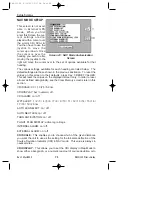
Pressing Key 3, AUTO LOCK, on 

Screen 26,

 Pin Change & Power On

Lock Enable Screen, allows you to switch the Auto Power-On Lock secu-
rity feature ON or OFF.  If you ENABLE the Power-On Lock, the unit will
require your PIN to be entered every time you or anyone else switches it
on. Although, as mentioned previously, so long as the Power-On Lock
has not been activated, you can key in as many PIN attempts as you
wish, once it has been ENABLED however the situation changes
entirely.

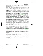
If an incorrect PIN is then entered three consecutive times at the switch-
on stage, the unit will lock out and display 

Screen 55

 (see 

Appendix 1).

If this happens to you, in order to re-activate the unit, you will have to
telephone Honeywell or your Bendix/King dealer (or Skyforce Avionics
Ltd. if in the United Kingdom).  You will require the Serial Number of your
unit and the Lock-Out Number, which you can read from the top of

Screen 55.

 The operator at your dealer or at Honeywell will verify these

details and check them against the Honeywell database and register of
stolen units.

Once the operator is satisfied that the unit has not been stolen and that
you are the officially recognized owner, you will be given an Unlock Code
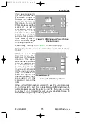
Number. This Unlock Number is a 10-digit number. In order to unlock
your unit you must now enter this number correctly into your unit, still
using 

Screen 55.

  The digits will replace the question marks as each one

is keyed in.  The unit regards the Unlock Number as having been
entered as soon as the last digit has been keyed in.  Every time an incor-
rect Unlock Number is entered, the unit will generate a new LOCK OUT
number.  This makes it impossible for a would-be thief to stumble upon
the Unlock Number by trial and error.  The odds against a thief guessing
the correct Unlock Code Number are 10 million to 1.  

If you do ever get into a Lock-Out situation and then re-activate your unit
with the Unlock Code Number received from Honeywell, remember that
no matter what PIN you were using before, the PIN will now have been
reset to the default digits of 1234.

NOTE:

Be very careful if you activate the Auto Power On Lock feature.  Locking
yourself out of the system can be very inconvenient.

96

Rev 1  Mar/2000                         

KMD 150 Pilot's Guide 

Setup Screens

KMD 150 PG  5/12/00 12:57 PM  Page 96

Summary of Contents for KMD-150

Page 1: ...Multifunction Display GPS Pilot s Guide KMD 150 Rev 1 Mar 2000 006 18220 0000 Software Revision 1 10 or Higher N Cover 3 17 00 1 59 PM Page 1 ...

Page 2: ...rt of this document review for export license requirement is needed COPYRIGHT NOTICE 2000 Honeywell International Inc Reproduction of this publication or any portion thereof by any means without the express written permission of Honeywell International Inc is prohibited For further information contact the Manager Technical Publications Honeywell Business General Aviation One Technology Center 2350...

Page 3: ...TRODUCTION 17 INITIALIZING YOUR UNIT 17 SOFTWARE STRUCTURE 18 SELECTING DEMO MODE 19 DATABASE SELECTION 20 A QUICK WORD ON DIRECT TOS AND FLIGHT PLANS 20 VISUAL DIRECT TO AND DATA INTERROGATION 21 DIRECT TO A SPECIFIC LATITUDE AND LONGITUDE 21 MANUAL DIRECT TO AND DATA INTERROGATION 22 EDITING CREATING A USER WAYPOINT MANUALLY 22 EDITING CREATING A USER WAYPOINT VISUALLY 23 SAVING A USER WAYPOINT ...

Page 4: ...ND INITIALIZATION 34 MAIN MENU SCREEN 35 NOTE PAD SCREEN 35 GPS STATUS SCREENS 37 ADJUSTING TIME AND DATE 40 SETTING LOCAL TIME OFFSET 40 SETTING PRESENT POSITION 41 DATA INPUT EXTERNAL GPS MODE 43 DISPLAY OF HOST FLIGHT PLAN DATA 43 Bendix King Data Format 43 NMEA and Northstar data 44 FLIGHT PLANNING SCREENS 45 USER WAYPOINTS 45 Basic User Waypoints 45 Marker User Waypoints 45 User Defined Airpo...

Page 5: ...RAPHICAL DIRECT TO 61 Airport Information 62 Navaid Information 62 General Icon Information 63 Airspace Interrogation 63 NAV MENU SCREENS 65 SELECTING A FLIGHT PLAN 67 TEN NEAREST AIRPORTS 68 NAVAIDS 70 MAP MODE WITH NAV INFORMATION 73 VIEWING ENROUTE ETA S PERFORMING A DIRECT TO ON TOP OF FLIGHT PLAN 75 Performing A Direct To On Top of A Flight Plan 75 Performing a DIRECT TO a point not in the ac...

Page 6: ...FUEL PLANNING 84 SUNSET SUNRISE CALCULATOR 86 SETUP SCREENS 87 MAP SETUP SCREENS 87 Settings Available 88 NAV MODE SETUP 92 PERSONAL IDENTIFICATION NUMBER PIN SETUP 94 Auto Power On Lock 96 INSTALLATION AND DIAGNOSTIC SCREENS 97 Screen Position Setup 97 View Logs 98 Engineering Log 98 GPS Receiver Information Log 98 Clear Memory 99 Data In Out 100 External GPS Data Input Option 101 Output Test 102...

Page 7: ... Power up 110 Continuous and Operator initiated Self Test 110 Heading Stabilization 110 Clear all Discharge Points 111 Switch Between Weather Views 111 Switch Between WX Display Modes 111 Changing Display Range 111 Operation in Stormscope Mode with Nav Overlay 112 Operation in Map Mode 112 Error Messages 113 Non Fatal Faults 114 Recoverable Faults 114 Heading Related Faults 114 Non Recoverable Fau...

Page 8: ...Thunderstorms 123 Special Patterns 124 Randomly Scattered Discharge Points 124 Cluster and Splattering Within 25nm 125 Discharge Points Off Aircraft s Nose 126 Line of Discharge Points While Taxiing 127 Developing Cluster Within the 25nm Range Ring 128 DEMO MODE 129 STORMSCOPE DEMO MODE 130 APPENDIX 1 WARNING SCREENS 131 RAM LOST WARNING 131 MEMORY BATTERY WARNING 131 PIN LOCK WARNING 132 LOCK OUT...

Page 9: ...ICAO CODES 137 APPENDIX 3 HOW DOES GPS WORK 147 WHAT IS GPS 147 HOW DOES GPS WORK 147 ACCURACY AND RELIABILITY 149 APPENDIX 4 DIFFERENTIAL FUNCTIONS 151 WHAT IS DGPS 151 HOW DOES DGPS WORK 151 USE OF DGPS 152 APPENDIX 5 DATABASE INFORMATION 153 DATABASE CYCLE INFORMATION 153 Table of Contents vii KMD 150 Pilot s Guide Rev 1 Mar 2000 toc 3 17 00 2 17 PM Page vii ...

Page 10: ...Table of Contents viii KMD 150 Pilot s Guide Rev 1 Mar 2000 Intentionally left blank toc 3 17 00 2 17 PM Page viii ...

Page 11: ...reen 11 Flight Plan Selection Screen 50 Screen 12 Flight Plan Program Edit Screen 51 68 Screen 13 Database Selection Screen 53 Screen 15 Temporary Waypoint Input Screen 54 Screen 16 Item Selection Screen 54 Screen 19 View and Edit Flight Plans On Map Screen 56 Screen 20 Demo Mode Setup Screen 129 Screen 21 Setup Cover Screen 87 Screen 22 Map Customization Screen 87 Screen 22A Point Features Data C...

Page 12: ...Map Mode with Joystick Active Screen 61 Screen 40 Map Mode Airport Info Screen 62 Screen 40A Map Mode Navaid Information Screen 62 Screen 40B Airspace Information Screen 64 Screen 40C Map Mode General Information Screen 63 Screen 41 NAV Menu Cover Screen 65 Screen 41A View ETA s and Direct To Screen 75 Screen 42 Flight Plan Selection Screen 67 Screen 43 Ten Nearest Airfields Screen 68 Screen 44 Ai...

Page 13: ... Screen 131 Screen 54 Power On Security PIN Entry Screen 132 Screen 55 Lockout Screen 132 Screen 56 Flight Plan Change Warning Screen 133 Screen 57 E6 B Calculator Cover Screen 81 Screen 58 Density Altitude True Air Speed Winds Aloft Screen 81 Screen 59 VNAV Setup Screen 83 Screen 60 Trip Fuel Flight Plan Select Screen 85 Screen 61 Sunset Sunrise Calculator Screen 86 Screen 62 Notepad Screen 35 Ta...

Page 14: ...Table of Contents xii KMD 150 Pilot s Guide Rev 1 Mar 2000 Intentionally left blank toc 3 17 00 2 17 PM Page xii ...

Page 15: ...talled We thank you for your decision to purchase a KMD 150 and wish you many happy and safe hours flying WARNING The Global Positioning System GPS satellite constellation is oper ated by the Department of Defense DOD of the United States which is solely responsible for its accuracy and maintenance Although declared fully operational on July 17 1995 the system is still under development and subjec...

Page 16: ...numeric any of the following characters b is a space b ABCDEFGHIJKLMNOPQRSTUVWXYZ0123456789 Baud bits per sec Barometric Altitude pressure altitude corrected for barometric altimeter setting Bearing To User Waypoint bearing from the present position to the active user waypoint measured clockwise relative to true or magnetic north true is implied unless magnetic is specified Cross Track Error dista...

Page 17: ...nimum off route altitude for any sector within a 10 nm square centered at a given position A minimum off route altitude of 7000 feet or less clears all known obstructions and terrain in a sector by 1000 feet a minimum off route altitude greater than 7000 feet clears all terrain by 2000 feet A sector is an area bounded by a 1o latitude longitude grid Scrolling Region a set of consecutive cursor fie...

Page 18: ... true or magnetic north true is implied unless magnetic is specified ACRONYMS AND ABBREVIATIONS AC Alternating Current ACT Active user waypoint or flight plan ADF Automatic Direction Finder AGL Above Ground Level ANSI American National Standards Institute APT Airport ARTCC Air Route Traffic Control Center ASCII American Standard Code for Information Interchange ATC Air Traffic Control ATF Aerodrom...

Page 19: ...ght Instrument System ELT Emergency Locator Transmitter ESA Enroute Safe Altitude ETE Estimated Time Enroute FAA Federal Aviation Administration FAR Federal Aviation Regulations FPL Flight Plan FPM Feet Per Minute FSS Flight Service Station ft feet FT Feet G Gravitational Acceleration 32 2 ft sec2 19 3 kt sec2 GAL Gallons GPS Global Positioning System hr hour HSI Horizontal Situation Indicator Hz ...

Page 20: ... LONG Longitude LRU Line Replaceable Unit m meters mA milliamperes MATZ Military Air Traffic Zone MAHP Missed Approach Holding Point MAP Missed Approach Point mB millibars MF Mandatory Frequency MHz Megahertz mi statute miles min minutes MOA Military Operation Area MSA Minimum Safe Altitude MSL Mean Sea Level msec milliseconds NDB Non Directional Beacon nm Nautical Miles NPA Non Precision Approach...

Page 21: ...AT Static Air Temperature sec seconds SID Standard Instrument Departure SNR Signal to Noise Ratio STAR Standard Terminal Arrival Route SUP Supplemental User Waypoint TAS True Airspeed TAT Total Air Temperature TD Time Difference TMA Terminal Control Area TOPO Topographical Data i e coastlines terrain rivers lakes etc TSO Technical Standard Order UTC Universal Coordinated Time same as Greenwich Mea...

Page 22: ...8 Rev 1 Mar 2000 KMD 150 Pilot s Guide W Watts wpt Waypoint µsec microsecond µV microvolts Ω Ohms C degrees Celsius F degrees Fahrenheit Introduction KMD 150 PG 5 12 00 12 56 PM Page 8 ...

Page 23: ...t of this manual for reference For those users who wish to get stuck into operating the system immediately the Quick Reference Section of the manual has been designed to get you up and running The operating system of the Bendix King KMD 150 keeps to a minimum the number of key presses necessary to activate the various functions especially those most frequently used in the air The provision of a jo...

Page 24: ...tion is performed the previous screen is then displayed All screen drawings show the KMD 150 running from it s internal GPS receiver Variations affecting the KMD 150 when connected to an external GPS are described in the accompanying text SELECTABLE GPS DATA SOURCE The KMD 150 is available with or without an internal GPS receiver The internal GPS version of KMD 150 has a built in eight channel par...

Page 25: ... map screens along with a visual and aural warning that there are thunderstorms in your vicinity SOFTWARE ARCHITECTURE The software in your KMD 150 unit is tree structured An analogy can therefore be drawn between the trunk of a tree and MAIN MENU MAIN MENU is the heart of the operating structure and can be accessed by pressing the HELP key after switching on the unit or pressing the MAIN MENU key...

Page 26: ... active NOTE PAD Allows up to 4000 characters of text previously down loaded from a PC using Flight Manager tm software to be viewed This key in only available if DEMO MODE is not running DEMO MODE can only be selected from the first screen when switching on the unit E6 B CALC Allows the E6 B Calculator to be used TAS WIND Allows density altitude TAS and winds aloft to be calculated NAV Allows ver...

Page 27: ...sfies the minimum runway length and surface requirements NEAR NAVAID Allows emergency search of 10 nearest navaids VORs and NDBs providing information and DIRECT TO capability SAVE WPT Allows your present co ordinates to be saved in the next available user waypoint number DIRECT TO Allows the user to perform a DIRECT TO any point in the internal or user defined database It may also be used to obta...

Page 28: ... in brackets is the height of the obstacle in FEET AGL TERRAIN AND URBAN AREAS DISPLAY On all map screens the land is shaded to show rising ground in seven elevation levels similar to those seen on a paper chart In addition all built up or urban areas are shaded light gray The levels and colors for the terrain shading are TERRAIN Color ATI Level AMR PAI Level Light Green Less Than 500 feet Less Th...

Page 29: ...rious types of information are stored in order to make best use of the equip ment The EPROM s Erasable Programmable Read Only Memory are in the database card and are used to hold the operating system and the database The database card can be replaced periodically in order to upgrade the operating system and update the database The RAM Random Access Memory is built into the unit and is used to stor...

Page 30: ...16 Rev 1 Mar 2000 KMD 150 Pilot s Guide General Information Intentionally left blank KMD 150 PG 5 12 00 12 56 PM Page 16 ...

Page 31: ...con trol The joystick allows movement of the pointer in MAP mode and is used for all forms of data entry or selection The appro priate key labels for a particular page are configured in software and drawn alongside the appropriate rubber key The rotary brightness control is used for adjusting the brightness of your screen INITIALIZING YOUR UNIT This procedure should have been carried out by your i...

Page 32: ...cted to an external GPS the KMD 150 unit will self initialize SOFTWARE STRUCTURE Since the software is tree structured an analogy can be drawn between the trunk of a tree and MAIN MENU This can be accessed after pow ering on the unit and pressing the HELP key MAIN MENU has 5 main software branches which are as follows GPS STATUS STORM SCOPE Shows satellite signal strength allows UTC Local Offset D...

Page 33: ...he unit will automatically be configured to accept data from the external GPS LORAN SELECTING DEMO MODE Demo Mode allows you to become familiar with handling your unit on the ground by turning it into a simulator Demo Mode can only be activated in the first title screen avail able at power on and will automatically be disabled if your unit receives valid GPS data Press DEMO MODE in the title scree...

Page 34: ...m is displayed press SELECT to select the item If the item required is in an aero nautical database i e AIRPORT VOR etc you may well have the ability to narrow the area of search by selecting a two letter identify in the AREA field For a com plete list of two letter ICAO identifiers please refer to Appendix 2 in this manual If the label in the AREA field says ALL then the search will include all c...

Page 35: ...eld If you wish to invoke the DIRECT TO function press the DIRECT TO key not available in External GPS Mode The unit will then provide you with full navigation information to reach this point Alternatively if you wish to obtain more information on a specific data point whether it is an airport a section of controlled airspace or a navaid move the pointer onto it and press the MORE INFO key Once th...

Page 36: ... displayed If you are running a DIRECT TO an item you can discontinue the navigation by pressing the DIRECT TO OFF key This function is not available in External GPS Mode EDITING CREATING A USER WAYPOINT MANUALLY From MAIN MENU select the FLIGHT PLAN key followed by USER WPTS Use the joystick to select the desired user waypoint number or name Then press the EDIT key and use the joystick to edit th...

Page 37: ...the first available memory location Any user waypoint can be removed by moving the pointer over it and pressing the DELETE WPT key If the user waypoint that you wish to delete is in a stored Flight Plan the message PRESENT IN FLIGHT PLAN will be displayed A second press on the DELETE WPT key will however remove it moving the joystick shall cancel the delete Use the PREV PAGE key to return to MAIN ...

Page 38: ...t the FLIGHT PLAN key followed by EDIT FPLN Use the joystick to select the desired flight plan number and then press SELECT To insert an item press INSERT ITEM and follow the Database Selection process explained earlier in this section of the manual To remove an item from the flight plan move the cursor over the item using the joystick and press DELETE ITEM A flight plan can be systematically buil...

Page 39: ... in the next available memory location To systematically create additional legs draw a line from the waypoint marked E with the pointer to the next waypoint and press ADD WPT again You will notice that the last point in the Flight Plan will always be labeled E Once you have finished building the Flight Plan press PREV PAGE If you wish to add a new waypoint to a flight plan which you have stopped b...

Page 40: ...n MAP mode can be varied from Small Text to Large Text to a CDI Pseudo HSI display In all three MAP MODES there are a fur ther two options which is either TOPO ON or TOPO OFF In the TOPO ON mode all classes of data can be set to a specific color In the TOPO OFF mode all cartographic data is auto matically removed and the Jeppesen Nav Data is presented on a black background The MAP MODE can be chan...

Page 41: ... to edit the Flight Plan Use the joystick to move a BLACK high light over END LAWRENCE then press DIRECT TO This function is not available in External GPS Mode TEN NEAREST SEARCH The ten nearest airports or navaids can be dis played by either pressing NAV MENU or DIRECT TO in MAP mode fol lowed by either NEAR APTS for airports or NEAR NAVAID for navaids The desired information will be pre sented d...

Page 42: ...p AIRPORT NAMES Labels airports in MAP MODE either with ICAO code airport or city names MAP UNITS Sets all map units to ether nau tical miles statute miles or kilometers If miles are selected all lengths and altitudes will be reported in feet If kilo meters are selected all lengths and altitudes will be reported in meters COORD SYSTEM Determines whether the unit operates with refer ence to Lat Lon...

Page 43: ... CLEAR LOG key in the Clear Memory screen Please refer to the Clear Memory section The flight can be replayed in DEMO MODE Refer to the Selecting DEMO MODE section POSITION REF Defines the reference to which your position is given in MAP MODE either to all available data VORs only or VORs and Airports only The following screens are accessed by repeatedly pressing the NEXT key They allow you to cho...

Page 44: ...s in nautical miles AUTO LEG SELECT When switched on the unit will automatically determine which is the most appropriate leg to fly when calling up a flight plan AUTO NEXT LEG When switched on the unit will automatically sequence you on to the next waypoint in a flight plan when it has deemed that the current waypoint has been passed When switched off the user will be expected to press the NEXT LE...

Page 45: ... parts of your units memory press SET UP in MAIN MENU followed by INST DIAGS and CLEAR MEMORY You will then be asked to enter your PIN Unit default is 1234 You are now in the Clear Memory screen Each block of memory in your unit can be cleared down individu ally CLEAR FLPNs will remove all your flight plans CLEAR WPTS will remove all your user waypoints CLEAR SETUP will restore all the default set...

Page 46: ...32 Rev 1 Mar 2000 KMD 150 Pilot s Guide Getting Started Intentionally left blank KMD 150 PG 5 12 00 12 57 PM Page 32 ...

Page 47: ... as shown here Key 1 calls Screen 2 which is the Main Menu Screen Key 2 calls Screen 7 which is the Flight Planning Mode Cover Screen Key 3 calls Screen 20 which is the Demo Mode Setup Screen If since being switched on the unit has received valid fix information from the internal GPS receiver Key 3 DEMO MODE will for safety reasons default to NOTE PAD and call screen 62 This also applies if the un...

Page 48: ...played Refer to Appendix 1 3 A check of the internal Lithium battery voltage If the internal battery voltage is low Screen 52 Internal Battery Warning Screen will be dis played Refer to Appendix 1 4 A check to see whether the Automatic Power On Lock function has been enabled see Screen 26 for further details If it is enabled Screen 54 Power On Security PIN Entry Screen will be displayed after 5 se...

Page 49: ...which is the NOTE PAD display screen and will also give access to Screen 57 which is the E6 B Calculator Cover Screen Refer to section on E6 B Calculator If Demo Mode has previously been activated Key 3 will read DEMO OFF Pressing DEMO OFF will then switch Demo Mode off and return to Screen 2 with Key 3 reading NOTE PAD Key 4 calls Screen 21 which is the Setup Cover Screen Key 5 calls Screen 38 or...

Page 50: ...r an unfamiliar destination etc Using the Flight Manager software from Honeywell you can prepare and store a library of Note Pad files and load the relevant one into your KMD 150 unit to suit your day s flying Screen 62 also gives access to the E6 B Calculator Screens 36 Rev 1 Mar 2000 KMD 150 Pilot s Guide Title and Help Screens KMD 150 PG 5 12 00 12 57 PM Page 36 ...

Page 51: ...less than three satellites in view and a fix can not be calculated This message is very rarely displayed DIFFERENTIAL This word will be displayed in conjunction with 2D FIX or 3D FIX and means that the KMD 150 has a fix and is also receiving differential correction signals from an external source Refer to Appendix 4 for further details concerning differential operation ACQUIRING means the unit is ...

Page 52: ... and a lower DOP This DOP figure is not measured in any specific units UTC DATE which is Universal or Greenwich Mean Time and Date LOCAL OFFSET which is the difference between UTC and local time LOCAL TIME which is calculated by adding Local Offset to UTC LAST FIX If the unit does not have a current valid fix this is the position at which it last had a fix If the unit has a fix this is the present...

Page 53: ... the satellite This usually takes around two minutes and is a function that is performed in the background even if the receiver has a fix AP Available for Position This means the satellite is fully locked in and tested and can be used for calculating position A minimum of three satellites are necessary for a 2D fix Key 1 returns to Main Menu Date Time Local Time Offset and Present Position can be ...

Page 54: ...ved up or down the first three characters of each month are scrolled together i e JAN FEB MAR APR etc Adjusting the year works in the same way Your KMD 150 unit is fully Year 2000 com pliant Only after pressing Key 1 SET is the new date saved The Time and Date will be automatically corrected as soon as the first satellite reaches TA time available status If any satellite is already at status TA or...

Page 55: ...r lati tude and longitude have been selected pressing Key 1 SET will enter the new latitude and longi tude and revert to Screen 3 Alternatively you can press Key 4 VIEW MAP and using the joystick simply point at your pre sent position When Screen 10A is dis played you can zoom in or out using Keys 2 or 3 By using the joystick you can bump the borders of the map window to view anywhere in the world...

Page 56: ... If the unit is receiving sufficient satellite signals to calculate a fix user entered latitude and longitude will be ignored Keys 3 and 4 give direct access to Time and Date adjustment GPS Status Screens KMD 150 PG 5 12 00 12 57 PM Page 42 ...

Page 57: ...RAN and choosing an option that corresponds to one of the compatible data input types listed previously Your installer should have carried this out Once a suitable data output type has been selected on the host GPS LORAN and it has a fix switch on your KMD 150 If the host GPS or LORAN is correctly connected switched on and outputting data your KMD 150 will automatically start to read and decode th...

Page 58: ... DME arcs turns and holds some Garmin GPS units send the flight plan information as if there was no arc or curved flight path Therefore the KMD 150 has no option but to connect the beginning and end waypoints of the arc or curve with a straight line Under these cir cumstances the line on the KMD 150 MUST BE IGNORED NMEA AND NORTHSTAR DATA If the host GPS is outputting NMEA data or Northstar M3 bin...

Page 59: ...cussed in the Map Mode Screens Section of this manual All user waypoints and flight plans are normally programmed before embarking on the trip and stored in the unit s user waypoint and flight plan library USER WAYPOINTS A user waypoint is a specific location anywhere in the world defined by an icon a name of up to nine letters or numbers and by a latitude and longitude In your KMD 150 there are t...

Page 60: ...me The Basic and Marker User Waypoint icons would then be superimposed on each other resulting in a single named Marker User Waypoint USER DEFINED AIRPORTS Owing to the fact that many private and unlicensed airports are not included within the Jeppesen database contained within your unit you have the opportunity to program up to 25 of your own USER DEFINED AIRPORTS User waypoints numbered 101 125 ...

Page 61: ...s Alternatively the joystick can be used to select a user waypoint alphabetically by name in a similar fashion by moving the cursor down to the NAME field As each user waypoint is selected the name latitude longitude icon and position fields are updated Empty user waypoints will be shown with dashes in the latitude and longitude fields and the default icon see Screen 22A Point Features Data Class ...

Page 62: ...o double the number of user points in the system to 1000 but it is essential to understand this feature thoroughly and to use it carefully Key 1 will return to the main Flight Planning Mode Cover Screen Once a user waypoint has been selected Key 2 gives access to the Manual User Waypoint Editing facilities Key 3 NEW WPT shall invoke the Manual User Waypoint editing with the next available empty wa...

Page 63: ...creen 8 without modifying the user waypoint information canceling all the changes you have made GRAPHICAL USER WAYPOINT EDITING When this Screen first appears after pressing VIEW MAP on Screen 8 User Waypoint Viewer Screen the selected user waypoint will be centrally positioned The joystick can be used to move the pointer The screen window can be moved around to display other areas of the map by b...

Page 64: ...ti cally be given the next available user waypoint number as a temporary name and the default icon but you can alter the name and icon later by using Screen 9 Manual User Waypoint Edit Screen EDITING USER AIRPORTS Whenever you select a user waypoint number between 101 and 125 in Screen 8 User Waypoint Viewer Screen Screen 8A User Airport Edit Screen will be displayed This is similar to Screen 8 bu...

Page 65: ... function please refer to the Trip Fuel Planning information in the E6B Calculator Section of this manual If you happen to access the previous Flight Plan Selection Screen while a flight plan is active and you subsequently dial up the active Flight Plan number you will find Key 5 changes to FPLN OFF and Key 1 goes blank As a safety measure the system will not allow you to edit the active Flight Pl...

Page 66: ... the flight plan start point to Waypoint 01 Moving the joystick down again would move the cursor down to 02 move the leg arrow down so that it is pointing between 01 and 02 and the figures next to the word LEG would then show the distance from 01 to 02 and so on The number next to the word FPLN is the total flight plan length from start to finish In addition as the cursor is moved up and down the ...

Page 67: ...nges to NEAR INTS Pressing this key will display the ten nearest intersections By moving the cursor you select the database that contains the item you are looking for whether to insert into your flight plan or to use as a DIRECT TO destination Once you have the cursor over the correct database touching Key 2 SELECT will move you onto the next selec tion process which is Screen 16 Item Selection As...

Page 68: ...ter of the first item in the selected database If AIRPORTS VORs NDBs INTs or AIRWAYS was selected on Screen 13 the first item in the data entry box on screen 16 is AREA This is an area filter that can be set to a specific ICAO country or area code If set to EG for example only items in British air space will appear in the list Similarly if set to LF only items in French airspace will be displayed ...

Page 69: ...same name To view the other airports with the same name move the cursor over the signs then scroll up and down through the other airports with the same name using the joystick On this Screen Key 5 labeled MORE INFO gives additional information about the selected item When an airport is selected but no runway the entry into your flight plan will be the name displayed followed by the airport s ICAO ...

Page 70: ... Waypoint This will place an S for Start next to the waypoint If no suitable data point or user waypoint is available beneath the pointer a new user waypoint will be created which can be name later by using Screen 9 Manual User Waypoint Edit Screen Then move the pointer to the second item or first waypoint in the flight plan and press Key 2 ADD WPT again This will place an E for End next to the wa...

Page 71: ...mple you wanted to add a new waypoint to the beginning of the flight plan illustrated previously simply move the pointer over FRESNO thereby highlighting it and then press Key 2 ADD WPT This will draw a line from the FRESNO to the pointer Next move the pointer until it is over the new waypoint highlight it and press Key 2 ADD WPT again You may continue to add further waypoints from the new startin...

Page 72: ...58 Rev 1 Mar 2000 KMD 150 Pilot s Guide Flight Planning Screens Intentionally left blank KMD 150 PG 5 12 00 12 57 PM Page 58 ...

Page 73: ...n either North Up mode or Track Up mode depending upon the setting you have made from Screen 22 Map Customization Screen NOTE When a map is displayed in North Up mode the icon shall be dis played The displayed data will be updated every second From this page if you press Key 1 Screen 2 Main Menu will take its place You can use Keys 2 and 3 at any time to zoom the map in and out to whichever one of...

Page 74: ... bearing from that airport that will be displayed even if there is a navaid user waypoint or town nearer All airport names are shown preceded by an asterisk character in order to distinguish them from towns or cities with similar names that may have significantly different locations If your position is found to be within five miles of a VOR beacon and more than five miles from an airport then your...

Page 75: ...ight up or down with the pointer You can still use Keys 2 ZOOM IN and 3 ZOOM OUT to zoom the map in and out When you are finished using this Screen press Key 1 RESET STICK and the joy stick pointer will vanish your display will return to Screen 38 and the map will be placed back in its present position at the zoom level it was at prior to activating the joystick If you don t move the joystick for ...

Page 76: ...k is not active can also access this Screen Allowing you to call up the item of interest from the airports database as if you were selecting it for a DIRECT TO If this Screen were entered this way Key 4 VIEW AREA would be present allowing you to not only view the appropriate airport data but also look at its position on the map NAVAID INFORMATION As explained previously you can access this Screen ...

Page 77: ...t also look at its position on the map GENERAL ICON INFORMATION As explained previously you can access this Screen from Screen 39 by placing the joystick pointer over any data icon that is not an air port VOR or NDB and pressing Key 4 MORE INFO All available infor mation concerning the chosen data item is then listed To obtain DIRECT TO for the chosen item all you have to do is press Key 5 labeled...

Page 78: ...ou zoom out dependant on the settings made in Screen 22C Airspace Data Class Setup Screen press MORE INFO key and Screen 40B Airspace Information Screen will be MORE INFO key and Screen 40B Airspace Information Screen will be displayed The information shown on this screen is all the infor mation from the internal Jeppesen database that is relevant to the airspace you have selected If some of the f...

Page 79: ...aphy and small NAV information text CDI TOPO ON Pseudo CDI style display which reverts to Topo Small Text map when joystick is hit not available in External GPS mode TOPO ON LARGE TXT Large map full color cartography and large NAV information text This will revert to the Topo Small Text map when the joystick is hit not available in External GPS mode TOPO OFF SMALL TEXT Large map black background n...

Page 80: ... WPT and your co ordinates will be saved as the next available user waypoint number Once the user waypoint has been saved the Screen will revert to Map Mode Screen 38 or 47 where the new user waypoint will already feature on the map This feature is not available when set to External GPS mode The text boxes on this screen give the following information Map Mode selected one of six options described...

Page 81: ... 2 will call Screen 12 Flight Plan Program Edit Screen for the selected flight plan If the selected flight plan is already running Key 5 will read FPLN OFF and Key 2 will be blank If the selected flight plan is not active Key 5 will be blank and Key 1 will read SELECT An active flight plan can be switched off at any time by pressing Key 5 FPLN OFF Pressing Key 5 will cancel the active flight plan ...

Page 82: ...n key 3 FIST LEG to fly from the first leg or key 5 SEL D LEG to fly from the highlighted leg NOTE If you have activated AUTO LEG SELECT on Screen 23 NAV Mode Customization Screen the nearest leg to your present position will auto matically be selected for you as soon as you enter Screen 12 TEN NEAREST AIRPORTS This Screen is accessed by pressing Key 3 NEAR APTS on Screen 41 NAV Menu Cover Screen ...

Page 83: ...urn from this Screen to Map Mode Screen 38 or 47 you simply press Key 2 To select another airport from the Ten Nearest Screen 43 you press Key 1 and if you want to see the list of ten nearest navaids simply press Key 4 which will take you directly to Screen 45 Ten Nearest Navaids To obtain a DIRECT TO for the chosen airport all you have to do is press Key 5 labeled DIRECT TO and you will switch ba...

Page 84: ... APTS will take you to Screen 43 giving you the list of the ten nearest airports To obtain a DIRECT TO for the chosen navaid all you have to do is press Key 5 labeled DIRECT TO and you will switch back to Screen 47 Map Mode with the selected DIRECT TO activated The Screen shown here shows the additional information about the navaid chosen on Screen 45 Ten Nearest Navaids From here by pressing Key ...

Page 85: ...r Waypoint on the Map Screen Screen 10A will revert back to screen 46 after 30 seconds with no key or joystick activity or can be cancelled by pressing Key 1 PREV PAGE To obtain a DIRECT TO for the chosen navaid all you have to do is press Key 4 labeled DIRECT TO and you will switch back to Screen 47 Map Mode with the selected DIRECT TO activated Nav Menu Screens KMD 150 PG 5 12 00 12 57 PM Page 7...

Page 86: ...72 Rev 1 Mar 2000 KMD 150 Pilot s Guide Nav Menu Screens Intentionally left blank KMD 150 PG 5 12 00 12 57 PM Page 72 ...

Page 87: ...es on or when the full scale value as set on Screen 23 is reached the internal and external alarms if switched on will beep at a rate of 2Hz for 5 seconds Key 5 will change to ALARM OFF and if you press this before the 5 sec onds are up this will silence the alarm When the alarm switches off automatically after 5 seconds Key 5 s label will go blank and have no function for 2 seconds then revert to...

Page 88: ...ic track the aircraft is traveling over the ground By comparing this with your magnetic heading you can make an estimate of the cross wind component To the right of TRK is GS This is the actual ground speed of the aircraft and is displayed in Knots if you set the map units to nautical miles on Screen 22 Map Customization Screen MPH if you set them to statute miles or KPH if the map units are set t...

Page 89: ... with the joystick If a waypoint further down the flight plan is selected then the DIRECT TO key is hit the unit will return to the map with a pseudo DIRECT TO run ning on top of the flight plan to the selected point The CDI will be cen tered and the FROM TO box will be replaced with a direct to box Once the selected point is reached the normal flight plan is automatically resumed This function is...

Page 90: ...g The next leg of the flight plan will now be displayed as a solid line If you pass the WPT the flag will change to WPT PASSED If the unit has been set up for AUTO NEXT LEG in Screen 23 then as the WPT is passed the unit will automatically revert to Screen 47 with all the new leg information Key 1 will go blank and inactive for two seconds then revert to MAIN MENU When the WPT ALERT alarm has been...

Page 91: ...Alarm value the WPT ALERT flag is shown and the internal and external alarms if switched on beep at a rate of 2Hz for 5 seconds The label for Key 1 changes to NAV OFF and that for Key 5 changes to ALARM OFF If you press Key 5 the audible alarm is silenced The alarm will switch itself off auto matically after 5 seconds then after a further 2 seconds the label for Key 5 will revert to DIRECT TO or D...

Page 92: ... revert to Topo On Small Text format to allow full use of map graphics When the joystick is reset or after 30 seconds with no key or joystick activity Screen 47A will be reinstated As Topo On Small Text Map Mode if the Topo Off Mode is selected the map will display aeronautical data only on a black background CDI MODE This Screen presents numeric navigation infor mation in small text but instead o...

Page 93: ...he CDI bar is not centered this indicates you are flying parallel to your desired track by however far the XTE is indicating The TO FROM flag will normally point up to indicate you are flying TO the waypoint When you pass your destination waypoint the TO FROM flag will point down to indicate you have passed the waypoint and you are now flying away FROM your destination As you pass your way point a...

Page 94: ...proach heading If the joystick is touched the display will immediately revert to Large Map format to allow full use of map graphics When the joystick is reset Screen 47B will be reinstated When flying with the CDI selected WPT ALERT messages and other warnings will be displayed in the CDI area Map Mode with Nav Information KMD 150 PG 5 12 00 12 57 PM Page 80 ...

Page 95: ...e Calculator page DENSITY ALTITUDE TAS WINDS ALOFT CALCULATOR On entry to this Screen a cursor will be positioned over the Indicated Altitude IALT data entry field TO CALCULATE DENSITY ALTITUDE DALT AND TRUE AIRSPEED TAS 1 Enter the altitude reading from your altimeter next to the IALT heading Default value on entry to Screen is internal GPS altitude for KMD 150 or 2000 if in External GPS mode 2 M...

Page 96: ...I Default value on entry to this Screen is GPS track The wind direction and speed WIND along with the head or tailwind component COMP will now be displayed in the lower half of the Screen When the wind has been calculated and you return to the map Screen by pressing Key 5 MAP a wind arrow will be displayed on screen cor rectly orientated and pointing at the aircraft icon to give a visual repre sen...

Page 97: ...t to GPS altitude if your unit has an internal GPS receiver or to 5000 feet if your unit is in External GPS mode or the last set value The TO value will default to 1500 feet or the last set value The BY value will default to 5 0nm or last set value and the AT value will default to 500fpm or last set value The DESCEND IN box will show an active countdown of the time left before you should start you...

Page 98: ...out the advi sory altitude will continue to count down until it reaches the TO altitude VNAV mode will then cancel automatically Should you wish to perform a DIRECT TO or select a new Flight Plan the VNAV Mode will need to be cancelled VNAV can be used for climbing as well as descending If the FROM alti tude is set to a lower value than the TO altitude then everywhere the words DESCENT and DESCEND...

Page 99: ...se speed of your aircraft Move the cursor down to FLOW HR and set the fuel flow per hour for your aircraft These settings will be permanently stored for later use Next move the cursor down and select the flight plan you want to perform the calculations for then move the cursor down again and scroll through the legs of your chosen Flight Plan As you scroll through the flight plan the seven calculat...

Page 100: ... can now alter the latitude longitude and time with the joystick or alter the latitude and longitude by choosing an item from the database Key 5 DATABASE calls Screen 13 Database Selection Screen fol lowed by 14 and 16 Once an item is selected this Screen returns with the item s latitude and longitude and name showing The POS SUNRISE and SUNSET fields are all re calculated each time you alter the ...

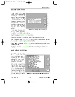
Page 101: ...gives access to Screen 23 NAV Mode Customization Screen only available when using the internal GPS Key 4 gives access to Screen 24 Personal Identification Number PIN Setup Screens Key 5 gives access to Screen 28 Installation and Diagnostic Screens MAP SETUP SCREENS To access Screen 22 Map Customization Screen press Key 4 SETUP in Main Menu followed by Key 2 MAP SETUP in Screen 21 Setup Cover Scree...

Page 102: ...lish French German Spanish MIN R W LENGTH selectable from 0 to 15 000 R W SURFACE REQUIRED hard soft hard EXTENDED TRACK on off AUTO ZOOM off on AUTO DECLUTTER on off KEY BEEP on off LOGGING RATE selectable between 000 and 999 secs POSITION REF all data VORs VORs Airports ORIENTATION This allows you to choose whether to have the map dis played with north at the top of the screen or orientated to h...

Page 103: ...ure simply by selecting EXT TRACK to OFF AUTO ZOOM Auto Zoom is a useful function to use as you approach your destination When flying the last leg of a Flight Plan or when flying a DIRECT TO as soon as the distance to the destination drops below 1 2 the scale bar setting the unit automatically zooms in so that the destina tion is always between 1 2 and one scale bars distance away For example if y...

Page 104: ...ass Setup Screens are accessed by repeatedly pressing Key 5 NEXT If there are two many items to be displayed on any of the data class screens they will be split across two screens It is impos sible to include every item from the database within the graphic map display especially when zoomed out to the smaller scale maps The Data Class Setup Screens allows you to choose the level of zoom at which y...

Page 105: ...ognizable form You will also notice that some settings have N A in their columns and are not adjustable These are items that have fixed values and are not user adjustable A good example of this is that you can not set up a color for the land in Topo Off Mode because no cartography is displayed in Topo Off Mode Not all data classes shown in the illustrations are available for all geo graphic areas ...

Page 106: ...ues on the displayed screen only In order to reset all user defined data globally see the Clear Memory screens later in this section CDI SCALE 0 3 1 0 2 5 5 0nm CDI DISPLAY bar numeric off CDI ALARM on off WPT ALERT 1 2 3 4 5 6 7 8 9 10 11 12 13 14 15 16 17 18 19 20 nm AUTO LEG SELECT on off AUTO NEXT LEG on off TURN ANTICIPATION on off FLIGHT PLAN DISPLAY active leg all legs INTERNAL ALARM on off...

Page 107: ...l be automatically selected You thus do not need to press Key 1 the NEXT LEG Key as this function produces the same effect automatically If you select AUTO NEXT LEG to OFF you will then need to activate the next leg in the Flight Plan manually by pressing Key 1 the NEXT LEG Key at the end of each leg otherwise your unit will continue to give you distance and bearing information to your previous wa...

Page 108: ...4 and 5 now labeled 1 2 3 and 4 as in the previous illustration The default PIN number that will be set when you receive the unit is 1234 As you enter each number by pressing each of the rele vant keys once in the order that matches the PIN each question mark in turn is replaced by an asterisk and the cursor moves one step to the right When the last digit is entered if you have failed to enter the...

Page 109: ...sor will be sitting over the first ques tion mark This repre sents the first digit of the PIN Your new PIN can be entered from here by pressing Keys 2 3 4 or 5 now labeled 1 2 3 and 4 in the previous illustra tion The numbers you enter will replace the question marks as they are entered and the cursor will step to the right When the fourth digit has been entered the new PIN will automatically be t...

Page 110: ... register of stolen units Once the operator is satisfied that the unit has not been stolen and that you are the officially recognized owner you will be given an Unlock Code Number This Unlock Number is a 10 digit number In order to unlock your unit you must now enter this number correctly into your unit still using Screen 55 The digits will replace the question marks as each one is keyed in The un...

Page 111: ...inadvertent erasure to the unit s memory Key 1 returns you to Screen 21 Setup Cover Screen Key 2 calls Screen 63 Screen Position Setup Screen Key 3 calls Screen 30 Engineering Log Screen Key 4 calls Screen 32 Memory Clear Entry Screen Key 5 calls Screen 35 Data In Out and Test Screen SCREEN POSITION SETUP Screen 63 is for use during manufacture to position the picture centrally in the viewable are...

Page 112: ...ans The Total Flight Hours is a value stored in exactly the same way as Total Hours Run the difference between these two figures being due to the fact that Flight Hours are totaled only during periods when the Ground Speed is above 30 knots Last Flight data is available only with the KMD 150 The Date and Start Time are logged as soon as the Ground Speed exceeds 30 knots and the Stop Time is logged...

Page 113: ...itch immediately to Screen 25 PIN INCORRECT and then take you back to Screen 28 the Cover Screen for Installation and Diagnostics If you do make a mistake however you are allowed to make as many attempts as you need to enter the correct PIN Be careful to handle operations from this Screen correctly otherwise you could lose valuable and important data from the memory of your unit If for instance yo...

Page 114: ... Settings for data output can be adjusted using the joystick and the options available are as follows The default set tings are listed first External GPS Source selected DATA OUTPUT OFF ECHO INPUT Internal GPS Source selected DATA OUTPUT OFF RS232 AR NAV NMEA 0183 Data output when using an external GPS receiver is limited to echoing the data input This provides a useful RS232 buffer for connecting...

Page 115: ...will not be available When KMD 150 is used with an external GPS source the data output will be limited to OFF and ECHO INPUT The second box is for information only and will only appear if the GPS SOURCE is set to EXTERNAL or if the Stormscope interface is switched ON If the Stormscope interface is switched on the presence of incoming Stormscope data is indicated by the word YES next to the STORMSC...

Page 116: ... INPUT heading If the data being received contains valid fix information i e the host GPS has a fix the word YES will appear next to the DATA VALID heading Once the unit is receiving and validating the incoming data select PREV PAGE and return to the MAIN MENU Screen OUTPUT TEST If you are installing an Internal GPS version of the KMD 150 and have made connection to other avionics equipment on the...

Page 117: ...ACTIVE Ensure Nav Superflag is inactive WPT Alert OFF Ensure the WPT Annunciator is OFF ON Ensure the WPT Annunciator is ON Message Alert OFF Ensure the MSG Annunciator is OFF ON Ensure the MSG Annunciator is ON Message Audio OFF Check Audio output is OFF ON Check Audio outputs is ON OBI RMI VALID Ensure that OBI RMI output reads the selected value INVALID Ensure that the OBI RMI is INVALID OBI SE...

Page 118: ...104 Rev 1 Mar 2000 KMD 150 Pilot s Guide Setup Screens Intentionally left blank KMD 150 PG 5 12 00 12 58 PM Page 104 ...

Page 119: ...ransmitter and no harmful transmissions The system operates as well on the ground as in the air thereby giving the pilot important planning informa tion even before takeoff Figure 13 1 Functional Diagram FUNCTIONAL DESCRIPTION The antenna detects the electric and magnetic fields generated by intra cloud inter cloud or cloud to ground electrical discharges that occur within a 200 nm radius of the a...

Page 120: ...isplay mode is selected the KMD 150 immediately plots an x symbol discharge point on the display for each individual discharge it detects within the selected range and view The strike display mode plots discharge points on the display in relation to where the discharges are actually detected instead of plotting them close to an associated group of discharge points as is done in the cell display mo...

Page 121: ...together the opposing air currents are the greater the shearing force of the air currents b The friction between the opposing air currents causes electrical charges in the area to separate As positive and negative electrical charges are separated they accumulate in masses of similar charges positive charges near the top of the cloud and negative charges near the bottom c Electrical discharges occu...

Page 122: ...ges you ve found the wind shear Figure 13 3 Discharge Rate a Function of Wind Shear STAGES OF A THUNDERSTORM All thunderstorms begin as cumulus clouds build to an intense mature stage and finally dissipate Each of these stages in the life of a thunder storm present a different set of dangers to aircraft Your Stormscope system maps all stages in the life of a thunderstorm so that you won t be caugh...

Page 123: ...harges The WX 500 analyses the unique characteristics of these signals their signal strength and their varying rates of recurrence to determine the location and intensity of the thunderstorms that gener ated the discharges The WX 500 can receive radiated electromagnetic signals from electrical discharges up to 200 nm away The cumulus stage of a thunderstorm usually precipitation free is unlikely t...

Page 124: ... power up self test the WX 500 performs a continuous self test Items tested include antenna operation microprocessor func tions memory and heading inputs This continuous self test is per formed several times each minute There are also provisions for an installer initiated self test that can be executed through the Stormscope setup screen HEADING STABILIZATION The heading stabilization feature auto...

Page 125: ...urrently selected weather display mode is indicated on the top left of the screen and will toggle between CELL and STRIKE with each press of the joystick The mode selected here will remain in effect until you change it even if the unit is turned off and back on CHANGING DISPLAY RANGE To change the displayed range of the Stormscope screen press either the Zoom In or the Zoom Out keys With each pres...

Page 126: ...the dedicated Stormscope screens on the KMD 150 It is also possible however to see thunder storm cell or strike data while in Map Mode if you select the lightning icons to be shown refer to the Map Setup screens When lightning is first plotted on the map a LIGHTNING message will be given at the bottom of the screen NOTE Lightning data will only be displayed on the map if a heading reference is ava...

Page 127: ...se error messages enable your authorized Stormscope dealer or BFG Avionics Systems factory service personnel to quickly diagnose and correct the fault Table 13 1 lists all the possible error messages the probable causes and the recommended actions Table 13 1 Error Messages Rev 1 Mar 2000 KMD 150 Pilot s Guide 113 Stormscope Operation KMD 150 PG 5 12 00 12 58 PM Page 113 ...

Page 128: ... goes away The error mes sage will disappear within 10 seconds after the fault goes away The fol lowing is an example of a recoverable fault Heading Related Faults During a heading fault the KMD 150 will automatically revert to using GPS track information assuming you are moving in excess of 3 knots in lieu of the now failed heading information The ERROR message will stay on screen until the headi...

Page 129: ... the screen Avoid the clusters and you ll avoid the thunder storms In the cell display mode even a single discharge point may rep resent thunderstorm activity and should be avoided INTRODUCTION The following examples are designed to help you relate the patterns of s or x s on the Stormscope screen to the size and location of thunder storms that may be near your aircraft A black and white grid in t...

Page 130: ...eract radial spread BFGoodrich Avionics Systems applied its extensive research in lightning detection to develop enhanced lightning positioning algorithms These algorithms used only in the cell display mode greatly reduce radial spread and improve the depiction of thunderstorms on the display The strike display mode does not use the enhanced lightning positioning algorithms instead it uses technol...

Page 131: ... 1 indicating greater electrical dis charge activity All three clusters however must be avoided because you can t necessarily determine the severity of thunderstorms based strictly on the number of discharge points For example in the western United States a severe thunderstorm may only have a few electrical dis charges Figure 13 5 Three Clusters Within 200 nm Stormscope Operation KMD 150 PG 5 12 0...

Page 132: ...o 200 nm Cluster 2 is now more defined and the discharge points are larger The interpretation of cluster 2 remains the same a moderately active thunderstorm at azimuth 4 00 range 75 nm You ll notice on the right hand Stormscope screen strike display mode that there is less radial spread than there was in the 200 nm range It is true in general that radial spread is reduced on the shorter ranges Fig...

Page 133: ...Stormscope screen can be interpreted as representing one thunderstorm cell at 5 30 about 150 nm from the aircraft and another thunderstorm cell at 1 00 about 100 nm from the aircraft The cluster at 1 00 has less radial spread in the strike display mode and fewer discharge points than the cluster at 5 30 indicating a lower rate of electrical activity Both clusters must be avoided Figure 13 7 Two Cl...

Page 134: ...ms Range Set at 200 nm Figure 13 8 shows the Stormscope screen in the 360 weather view at the 200 nm range Two thunderstorms appear almost as one cluster of discharge points off the nose of the aircraft centered 180 nm away A second cluster at 9 30 indicates a storm system that contains three thun derstorms Figure 13 8 Range Set at 200 nm Stormscope Operation KMD 150 PG 5 12 00 12 58 PM Page 120 ...

Page 135: ...ro gressed 100 nm The two thunderstorms off the nose of the aircraft appear to have expanded horizontally on the screen This effect is normal anytime you get closer to a storm The line of thunderstorms pre viously at 9 30 now appears at 8 30 Figure 13 9 Aircraft Progresses 100 nm Stormscope Operation KMD 150 PG 5 12 00 12 58 PM Page 121 ...

Page 136: ... aircraft appear in greater detail as two separate thunderstorms The thunder storms at 11 30 and 12 15 are centered 90 nm from the aircraft Information is now sufficient to map a Flight Plan around the thunder storms The WX 500plots discharge points within the selected range even if the points obscure the CELL or STRIKE display mode indicator as they do in Figure 13 10 Figure 13 10 Range Changes t...

Page 137: ...he aircraft has turned to the right to avoid the thunderstorms When con nected to a compatible heading system the Stormscope system auto matically rotates the existing discharge points to their correct position rel ative to the new heading Figure 13 11 Aircraft Turns To Avoid Thunderstorms Stormscope Operation KMD 150 PG 5 12 00 12 58 PM Page 123 ...

Page 138: ...scope screen as shown in Figure 13 12 Random discharge points are more likely to appear in the Stormscope system s strike display mode than in the cell display mode due to the cell display mode s clustering algorithm If you observe random discharge points continue to monitor the screen for developing clusters that indicate thun derstorm activity Figure 13 12 Randomly Scattered Discharge Points Sto...

Page 139: ...Switch to the other range set tings to ensure that there is no thunderstorm activity indicated along your intended path You ll notice in Figure 13 13 that the location of random individual dis charge points is about the same on both the cell and storm display modes This is true because in the cell display mode the Stormscope system plots every electrical discharge detected within the 25 nm range a...

Page 140: ... the aircraft could be caused by a strong thunderstorm just beyond the 200 nm range Another scenario might be that electrical discharge signals are arriving via atmos pheric skip from a distant thunderstorm well beyond the Stormscope range In either case no immediate action is required Figure 13 14 Discharge Points Off Aircraft s Nose Stormscope Operation KMD 150 PG 5 12 00 12 58 PM Page 126 ...

Page 141: ...en as shown in Figure 13 15 Similar concentra tions of discharge points across the screen may appear while taxiing due to electrical signals from nearby equipment such as arc welders or subway rails After passing the source of the interference press the CLR button Figure 13 15 Line of Discharge Points While Taxiing Stormscope Operation KMD 150 PG 5 12 00 12 58 PM Page 127 ...

Page 142: ...nderstorm 12 nm from the aircraft If you see a screen such as this with a developing cluster within the 25 nm range ring you should change course to avoid the storm and con tinue to monitor the Stormscope screen Figure 13 16 Developing Cluster Within 25 nm Range Ring Stormscope Operation KMD 150 PG 5 12 00 12 58 PM Page 128 ...

Page 143: ...l be the co ordinates of your last fix position Alternatively you can press Key 3 and select a start point from the built in database You can also set the airspeed at which you want to fly the demo to any thing between 000 and 999 Knots Once you have set your position and speed if you press Key 5 you will find Screen 38 Map Mode displayed and you are ready to start Demo Mode All map Screens that y...

Page 144: ...can be used to cancel Demo Mode STORMSCOPE DEMO MODE If you have a WX 500 Stormscope sensor connected to your KMD 150 entering Demo Mode on the KMD 150 will also cause the WX 500 to enter Demo Mode When in Demo Mode the WX 500 will output random storm patterns which will be received and interpreted by the KMD 150 in the normal way See STORMSCOPE OPERATION for fur ther details on the WX 500 interfa...

Page 145: ...ORY BATTERY WARNING This Screen will appear if during initialization the memory battery voltage is found to be low It can also appear at any time during operation if the internal battery falls below a pre determined limit By pressing Key 1 you can return to whichever Screen was showing before the low voltage condition was detected If this screen is displayed you should have your memory battery rep...

Page 146: ...aged to enter the correct PIN As the PIN is entered asterisk characters are displayed in place of the question marks Key 1 can be used as a Back Space Key LOCK OUT WARNING This Screen will only appear after three incor rect PIN s have been entered on Screen 54 or if when you switch the unit on the NVM is found to have accumulated three unsuccessful PIN input attempts The LOCK OUT number is a rando...

Page 147: ...ate the Auto Power On Lock feature Locking yourself out of the system can be very inconvenient NEW DATABASE CARD WARNING If during initialization the unit detects a new data base card the software will check through the Flight Plans programmed into the unit and validate the data Whenever you build a Flight Plan by using items from the database card the Name Lat and Long of each chosen item is copi...

Page 148: ...l read CHANGING DATABASE REFERENCE PLEASE CONFIRM Pressing Key 1 will change the database reference displayed on Screen 12 Flight Plan Program Edit Screen to OW indicating that this item is now an Old User Waypoint and is no longer accessible from any data base This check is carried out for every point in every Flight Plan and when ever discrepancies are found Screen 56 will appear on each occasio...

Page 149: ...s a low resolution map of the rest of the world The ten ICAO ARINC areas along with their three letter identifiers are AFR Africa CAN Canada EEU Eastern Europe EUR Europe LAM Latin America MES Middle East PAC Pacific SAM South America SPA South Pacific USA USA These areas are combined to produce three database cards covering the entire world that contain the following data AMR Americas comprising ...

Page 150: ...rence point clearance within these tiles Jeppesen define a reference point as a natural peak knoll hill etc or man made tower stack tank building etc object Jeppesen state that Grid MORA values clear all reference points by 1000 feet in areas where the highest reference points are 5000 feet MSL or lower MORA values clear all reference points by 2000 feet in areas where the highest reference points...

Page 151: ... this appendix Official Country State Name ICAO Jeppesen Standard Name State Area ACCRA FIR DG ACCRA FIR AFR ALGERIA P DEMOCRATIC REP OF DA ALGERIA DZA AFR ANGOLA REPUBLIC OF FN ANGOLA AGO AFR ANTANANARIVO FIR UIR FM ANTANANARIVO FIR UIR AFR ANTARCTICA AFR INDIAN OC F1 ANTARCTICA AFR AFR ASCENSION I FH ASCENSION SHN AFR BENIN PEOPLES REPUBLIC OF DB BENIN BEN AFR BOTSWANA REPUBLIC OF FB BOTSWANA BW...

Page 152: ...REPUBLIC OF FM MADAGASCAR MDG AFR MALAWI REPUBLIC OF FW MALAWI MWI AFR MALI REPUBLIC OF GA MALI MLI AFR MAURITANIA ISLAMIC REPUBLIC GQ MAURITANIA MRT AFR MAURITIUS FIR FI MAURITIUS FIR AFR MAYOTTE FM MAYOTTE MYT AFR MELILLA SPAIN GE MELILLA ESP AFR MOROCCO KINGDOM OF GM MOROCCO MAR AFR MOZAMBIQUE REPUBLIC OF FQ MOZAMBIQUE MOZ AFR N DJAMENA FIR UIR FT N DJAMENA FIR UIR AFR NAIROBI FIR HK NAIROBI FI...

Page 153: ...AN CAN BRITISH COLUMBIA CY BRITISH COLUMBIA CAN CAN CANADA CY CANADA CAN CAN MANITOBA CY MANITOBA CAN CAN NEW BRUNSWICK CY NEW BRUNSWICK CAN CAN NEWFOUNDLAND CY NEWFOUNDLAND CAN CAN NORTHWEST TERRITORIES CY NORTHWEST TERRITORIES CAN CAN NOVA SCOTIA CY NOVA SCOTIA CAN CAN ONTARIO CY ONTARIO CAN CAN PRINCE EDWARD ISLAND CY PRINCE EDWARD ISLAND CAN CAN QUEBEC CY QUEBEC CAN CAN SAINT PIERRE AND MIQUEL...

Page 154: ...LIA MNG EEU POLISH PEOPLES REPUBLIC EP POLAND POL EEU REPUBLIC OF ESTONIA EE ESTONIA EST EEU ROMANIA SOCIALIST REPUBLIC OF LR ROMANIA ROM EEU RUSSIAN FEDERATION UN RUSSIA RUS EEU RUSSIAN FEDERATION US RUSSIA RUS EEU RUSSIAN FEDERATION UM RUSSIA RUS EEU RUSSIAN FEDERATION UR RUSSIA RUS EEU RUSSIAN FEDERATION UE RUSSIA RUS EEU RUSSIAN FEDERATION UH RUSSIA RUS EEU RUSSIAN FEDERATION UU RUSSIA RUS EEU...

Page 155: ...SLANDS PORTUGAL LP MADEIRA IS PRT EUR MALTA REPUBLIC OF LM MALTA MLT EUR NETHERLANDS EH NETHERLANDS NLD EUR NORWAY EN NORWAY NOR EUR PORTUGUESE REPUBLIC LP PORTUGAL PRT EUR REPUBLIC OF SLOVENIA LJ SLOVENIA SVN EUR SANTA MARIA OCEANIC LP SANTA MARIA OCEANIC EUR SHANWICK OCEANIC EG SHANWICK OCEANIC EUR SPANISH STATE LE SPAIN ESP EUR SWEDEN KINGDOM OF ES SWEDEN SWE EUR SWISS CONFEDERATION LS SWITZERL...

Page 156: ...SAINT VINCENT THE GRENADINES TV ST VINCENT VCT LAM SAINT LUCIA TL ST LUCIA LCA LAM SAINT KITTS AND NEVIS TK ST KITTS KNA LAM SAN ANDRES COLOMBIA SK SAN ANDRES COL LAM TRINIDAD AND TOBAGO REP OF TT TOBAGO I TTO LAM TRINIDAD AND TOBAGO REP OF TT TRINIDAD TTO LAM TURKS AND CAICOS ISLANDS MB TURKS IS TCA LAM VIRGIN ISLANDS OF THE U S TI VIRGIN IS VIR LAM VIRGIN ISLANDS BRITISH TU BRITISH VIRGIN IS VGB...

Page 157: ... TURKEY REPUBLIC OF N CYPRUS LC TURKEY REP OF N CYPRUS TUR MES UNITED ARAB EMIRATES OM UNITED ARAB EMIRATES ARE MES Official Country State Name ICAO Jeppesen Standard Name State Area CAMBODIA STATE OF VD CAMBODIA KHM PAC CAROLINE ISLANDS PT CAROLINE IS PCI PAC CHINA THE REPUBLIC OF RC TAIWAN TWN PAC GUAM PG GUAM GUM PAC HAWAII PH HAWAII USA PAC HONG KONG VH HONG KONG HKG PAC JAPAN RJ JAPAN JPN PAC...

Page 158: ...FLK SAM FRENCH GUIANA SO FRENCH GUIANA GUF SAM GUYANA REPUBLIC OF SY GUYANA GUY SAM PARAGUAY REPUBLIC OF SG PARAGUAY PRY SAM PERU REPUBLIC OF SP PERU PER SAM SURINAME REPUBLIC OF SM SURINAME SUR SAM URUGUAY REPUBLIC OF SU URUGUAY URY SAM VENEZUELA REPUBLIC OF SV VENEZUELA VEN SAM Official Country State Name ICAO Jeppesen Standard Name State Area ANTARCTICA AUS NZ A1 ANTARCTICA AUS NZ SPA AUSTRALIA...

Page 159: ...EPUBLIC OF NV VANUATU VUT SPA WALLIS AND FUTUNA ISLANDS NL FUTUNA IS WLF SPA WALLIS AND FUTUNA ISLANDS NL WALLIS IS WLF SPA Official Country State Name ICAO Jeppesen Standard Name State Area ALABAMA K7 ALABAMA USA USA ARIZONA K2 ARIZONA USA USA ARKANSAS K4 ARKANSAS USA USA BAHAMAS COMMONWEALTH OF THE MY BAHAMAS BHS USA BERMUDA ISLANDS TX BERMUDA BMU USA CALIFORNIA K2 CALIFORNIA USA USA COLORADO K2...

Page 160: ...D STATES OF AMERICA USA USA OAKLAND OCEANIC CONTROL AREA K1 UNITED STATES OF AMERICA USA USA OHIO K5 OHIO USA USA OKLAHOMA K4 OKLAHOMA USA USA OREGON K1 OREGON USA USA PENNSYLVANIA K6 PENNSYLVANIA USA USA RHODE ISLAND K6 RHODE ISLAND USA USA SOUTH CAROLINA K7 SOUTH CAROLINA USA USA SOUTH DAKOTA K3 SOUTH DAKOTA USA USA TENNESSEE K7 TENNESSEE USA USA TEXAS K4 TEXAS USA USA UNITED STATES OF AMERICA K...

Page 161: ...atus and almanac orbital information and clock timing corrections The signals have been designed to be extremely resistant to interference from terrestrial radio transmissions electronic equipment and weather The technique used to establish position using these satellites is one of simple ranging In other words position is calculated from measurements of the distances between the observer and a nu...

Page 162: ...sal time the calculated distance from the satellite would have an error of 1 860 miles This problem is overcome by a second technique 2 Making use of an extra satellite In order to obtain a positional fix in three dimensional space it is necessary to know the exact distance to each of three satellites The exact distance is however not known because of the presence of an offset or error in the rece...

Page 163: ... on 1 57542 GHz only and is called the C A code C A stands for Coarse Acquisition This code is relatively simple compared to the P code and has a repeti tion rate of one millisecond The present maximum accuracy for receivers using the C A code is 15 meters There is the possibility however of this being intentionally degraded by feeding random errors into the satellite clocks to 100 meters for stra...

Page 164: ...OD can predict there may be a substantial break in coverage for civilian users is at a time of National Emergency when the whole system may be reverted to P code military operation only for strategic reasons How Does GPS Work KMD 150 PG 5 12 00 12 58 PM Page 150 ...

Page 165: ...l out all of the errors due to SA to orbital errors and to satellite clock inaccuracy It also greatly reduces any error caused by the atmospheric delay to radio signals What DGPS cannot correct for are only the inaccuracies due to the GPS receiver itself and possible multi path errors which like ghosting on a TV are due to secondary signals being received after reflection off local obstructions Th...

Page 166: ...before it becomes out of date USES OF DGPS Standard GPS provides very adequate accuracy for most navigational tasks but the additional precision available through DGPS opens up other possibilities in aviation and in many other spheres of activity Once the aviation authorities are prepared to approve DGPS based low visi bility approach and landing systems these could provide low cost preci sion fac...

Page 167: ...iewpoint that you continue to keep your database current The KMD 150 is not however an IFR primary means of navigation system Therefore its use as an advisory navigation system does not mandate that the database is current For GPS database subscriptions contact Navigation Services at the fol lowing numbers 1 800 247 0230 if calling within the United States or Canada 913 712 3145 if calling from ou...

Page 168: ...154 Rev 1 Mar 2000 KMD 150 Pilot s Guide Intentionally left blank KMD 150 PG 5 12 00 12 58 PM Page 154 ...

Page 169: ...siness General Aviation One Technology Center 23500 West 105th Street Olathe Kansas 66061 Telephone 913 782 0400 1999 Honeywell International Inc 006 18220 0000 Rev 1 Mar 2000 Printed in U S A n KMD 150 PG 5 12 00 12 58 PM Page 156 ...

Reviews: