


40
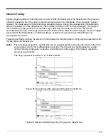
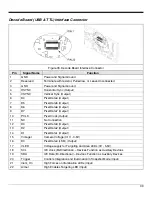
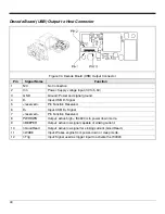
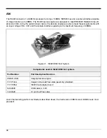
Decode Board (USB) Output to Host Connector
Figure 34. Decode Board (USB) Output Connector
Pin
Signal Name
Function
1 N/C
No
Connection
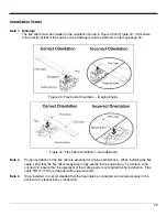
2
Vin
Power: Supply voltage input (3V to 5.5V)
3
GND
Ground: Power and signal ground.
4
D-
Input: USB D- Signal
5
<reserved>
Pin Function Reserved.
6
D+
Input: USB D+ Signal
7
<reserved>
Pin Function Reserved.
8
PWRDWN
Output: active high = IS4920 is in power down mode.
9
nBEEPER
Output: active low signal capable of sinking current.
10
nGoodRead
Output: active low signal for sinking current (Good Read).
11
nWAKE
Input: Wakes engine from power-down or sleep mode.
12
nTrig
Input: Signal used as trigger input to activate the IS4920