Honeywell HUPF Series Instruction Sheet Download Page 3

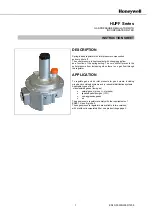
Gas pressure regulator with incorporated filter 

EN1C-0003NL05 R

1205


3

HUPF Series 


INSTALLATION 


Important 

1.  Read these instructions carefully. Failure to 

follow  the  instructions  could  damage  the 

product or cause a hazardous condition. 

2.  The  installation  has  to  be  carried  out  by 

qualified personnel only. 

3.  Carry  out  a  thorough  checkout  when 

installation is completed. 


Warning 

• 

Turn off gas supply before installation. 

• 

Do  not  remove  the  seal  over  regulator 

inlet  and  outlet,  until  ready  to  connect 

piping. 

• 

Do not remove the perforated diaphragm 

breather  cap  (3)  and  do  not  obstruct  the 

hole. 

• 

The  regulator  must  be  installed  so  that 

the  arrow  on  the  regulator  points  in  the 

direction of the gas flow. 


Mounting position 

To  ensure  perfect  regulator  operation,  regulator 

should  be  assembled  horizontally.  They  can 

however  be  installed  in  different positions up to an 

angle of 90

°


Mounting location 

Contact between the regulator and walls or a floor is 

not  permitted.  Maintain  a  distance  of  at  least  50 

mm. 

Note:   In case of the HUPF Series, the distance 

between  the  bottom and the ground must 

be  at  least  400  mm,  to  facilitate  filter 

cleaning and inspection. 


Main gas connection threaded regulators 

•  

Take care that dirt cannot enter the gas regulator 

during handling. 

• 

Ensure the gas flow in the same direction as the 

arrow on the housing of the gas regulator. 

• 

Use a sound taper fitting with thread according to 

ISO  7-1  (BS21,  DIN  2999)  or  a  piece  of  new, 

properly reamed pipe, free from swarf. 

• 

Do not thread or tighten the pipe or pipe fitting too 

far. Otherwise regulator distortion and malfunction 

could result. 

• 

Apply a  moderate  amount of good quality thread 

compound  to the pipe or fitting only, leaving the 

two end threads bare. PTFE tape may be used as 

an alternative. 

• 

In order to tighten the pipe in the regulator, do not 

use the sleeve of the upper cover as a lever but 

use  a  suitable  wrench  operating  on  the  wrench 

bosses. 

Main 

regulator 

connection 

flanged 

regulators 

• 

Take care that dirt cannot enter the gas regulator 

during handling. 

• 

Ensure the gas flow in the same direction as the 

arrow on the housing of the gas regulator. 

• 

Ensure that inlet and outlet flanges are in line and 

separated  from  each  other  enough  to  allow  the 

regulator  to  be  mounted  between  them  without 

damaging the gasket. 

• 

Place  gasket.  if  necessary  grease  it  slightly  to 

keep it in place. 

• 

Mount  gas  regulator  between  flanges  using  the 

bolts for each flange. 

Warning 

Tightness test after installation 

• 

Spray  all  pipe  connections and gaskets 

with  a  good  quality  gas  leak  detection 

spray. 

• 

Start  the  appliance  and  check  for 

bubbles.  If  a  leak  is  found  in  a  pipe 

connection, remake the joint. A gasket leak 

can  usually  be  stopped  by  tightening  the 

mounting  screws.  Otherwise  replace  the 

gas pressure regulator. 

Summary of Contents for HUPF Series

Page 1: ...ts the outlet pressure from increasing when there is no gas flow through the regulator APPLICATION To regulate gas and air inlet pressure for gas burners including mixed and combined systems and in industrial distribution systems Applicable types of fuel manufactured gases town gas natural gases group H methane liquefied petroleum gas LPG non aggressive gases air The gas pressure regulators comply...

Page 2: ... i e zero shut off Torsion and bending stress Pipe connections meet group 2 according to EN 88 1 requirements Set point accuracy According to EN88 1 class A group 2 Adjustment spring range Max allowed pressure Up to 1 bar without body damages Ambient temperature range 15 C 60 C Material of pressure receiving parts Elastomer EN549 Sealing elements Hydrocarbon resistant NBR rubber type NBR 70 Safety...

Page 3: ...he same direction as the arrow on the housing of the gas regulator Use a sound taper fitting with thread according to ISO 7 1 BS21 DIN 2999 or a piece of new properly reamed pipe free from swarf Do not thread or tighten the pipe or pipe fitting too far Otherwise regulator distortion and malfunction could result Apply a moderate amount of good quality thread compound to the pipe or fitting only lea...

Page 4: ...l Connection inch mbar A B C D E F HUPF015B110 1 2 500 138 1 2 175 HUPF020B110 3 4 500 134 3 4 175 HUPF025B110 1 500 134 1 175 HUPF032B110 1 1 4 500 194 1 1 4 255 HUPF040B110 1 1 2 500 194 1 1 2 255 HUPF050B110 2 500 236 2 316 HUPF050B310 DN50 500 352 DN50 349 HUPF065B310 DN65 500 350 DN65 427 HUPF080B310 DN80 500 350 DN80 434 HUPF100B310 DN100 500 415 DN100 502 ...

Page 5: ...he required outlet pressure by proceeding with step 1 to 4 of Outlet pressure adjustment section on this page Final checkout of the installation Set the appliance in operation after any adjustment and observe several complete cycles to ensure that all burner components function correctly MAINTENANCE The regulators are completely maintenance free In the event of a breakdown a general overhaul and f...

Page 6: ... 1000 Nominal flow rate m3 h Pressure drop mbar 1 2 3 4 1 1 1 4 1 1 2 2 DN65 DN80 DN100 Honeywell Manufactured for and on behalf of the Environmental and Combustion Controls Division of Honeywell Sàrl 1180 Rolle Z A Lá Piece 16 Switzerland by its Authorized Representative Automation and Control Solutions Combustion Controls Europe Honeywell BV Phileas Foggstraat 7 7821 AJ Emmen The Netherlands Tel...

Reviews: