background image

12

Controls and Functions

Back Panel Controls

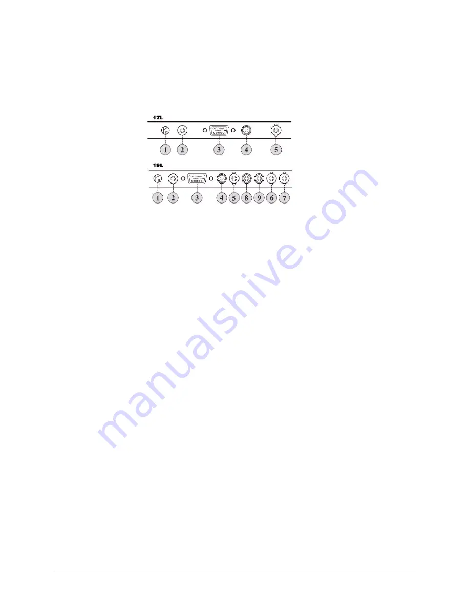
Figure 2

Back panel connectors

1.

Audio-in

2.

DC power-in

3.

VGA-in (D-Sub connector)

4.

Video-in (RCA)

5.

Video2-in (BNC)

6.

Video3-in (BNC)

7.

Video3-loop-out (BNC)

8.

Audio-in-Right (Video mode)

9.

Audio-in-left (Video mode)

How to Install the Power Cable:

1.

Plug the AC/DC adapter into the DC power-in.

2.

Connect the AC power cable to the adapter.

3.

Connect the VGA cable to the D-Sub connector.

4.

Plug the AC power cable connector into an AC power outlet.

Summary of Contents for HMLCD17L

Page 1: ...Document 800 00945 Rev A 09 07 User Manual HMLCD17L HMLCD19L L Series LCD Monitor ...

Page 2: ...Revisions Issue Date Revisions A Sept 2007 Initial Release ...

Page 3: ...enna Relocate the system with respect to the receiver Move the system away from the receiver Plug the system into a different outlet so that the system and the receiver are on different branch circuits If necessary consult a representative of Honeywell Inc or an experienced radio television technician for additional suggestions The following information is provided on the device or devices covered...

Page 4: ...dusty hallway 12 Do not expose the monitor to rain or use it near water in kitchens next to swimming pools etc If the monitor accidentally gets wet unplug it and contact an authorized dealer immediately You can clean the monitor with a damp cloth when necessary being sure to unplug the monitor first 13 Place the monitor on a solid surface and treat it carefully The screen is made of glass and can ...

Page 5: ...L Series LCD Monitor User Manual Document 800 00945 Rev A 5 09 07 Contents Controls and Functions 11 OSD Menu 13 Power Management 17 Specifications and Parts 18 Troubleshooting 21 ...

Page 6: ...6 Contents ...

Page 7: ...A 7 09 07 Figures Figure 1 Front panel controls 11 Figure 2 Back panel connectors 12 Figure 3 Color settings 13 Figure 4 Picture settings 14 Figure 5 Function settings 14 Figure 6 OSD Menu settings 15 Figure 7 Misc settings 15 Figure 8 Monitor dimensions 18 ...

Page 8: ...8 Figures ...

Page 9: ...ies LCD Monitor User Manual Document 800 00945 Rev A 9 09 07 Tables Table 1 Power Consumption 17 Table 2 LED Indicator 17 Table 3 Specifications list 19 Table 4 Pre Set Display Mode 19 Table 5 Parts list 20 ...

Page 10: ...10 Tables ...

Page 11: ...eatures OSD menu MPR II certified DDC1 and DDC2 plug and play functionality Full range power supply that auto adjusts to accept AC 100V to 240V and 50Hz to 60Hz Front Panel Controls Figure 1 Front panel controls 1 AUTO button 2 OSD t button 3 OSD s button 4 OSD MENU button 5 Power switch 6 LED Power indicator 1 2 3 4 5 6 1 2 3 4 5 HMLCD17L HMLCD19L ...

Page 12: ...RCA 5 Video2 in BNC 6 Video3 in BNC 7 Video3 loop out BNC 8 Audio in Right Video mode 9 Audio in left Video mode How to Install the Power Cable 1 Plug the AC DC adapter into the DC power in 2 Connect the AC power cable to the adapter 3 Connect the VGA cable to the D Sub connector 4 Plug the AC power cable connector into an AC power outlet ...

Page 13: ...elow To scroll through the main menu and select sub menu options use the s and t buttons on the front panel of the monitor To change a menu setting use the and options Color Figure 3 Color settings Contrast Increase or decrease the intensity lightness or dimness of the image Brightness Increase or decrease the intensity of the image Gamma Adjusts the level of the screen image Color Temp Select fro...

Page 14: ... up and down Phase Adjust the number of horizontal picture elements Clock Adjust the vertical noise of the screen image Sharpness Adjust background black level of the screen image Function Figure 5 Function settings Auto Adjust Select whether to enable the auto adjust feature of the monitor Auto Color Select whether to enable the auto color feature of the monitor ...

Page 15: ...tion OSD window horizontal position adjustment OSD V Position OSD window vertical position adjustment OSD Timer Set the OSD screen standby time Translucent Set the translucency of the OSD Misc Figure 7 Misc settings Signal Source Select the signal source for the monitor Mode Select Select the screen resolution Reset Selecting YES restores the factory defaults for the monitor ...

Page 16: ...16 OSD Menu Volume Adjust the monitor audio volume ...

Page 17: ...tage that the power management system is in is indicated by the LED on the monitor Table 1 Power Consumption Mode Power Consumption ON 50W or less STANDBY 3W or less SUSPEND 3W or less ACTIVE OFF 3W or less Table 2 LED Indicator Mode LED Color Monitor Operation ON Green Normal operation STANDBY SUSPEND ACTIVE OFF Yellow Screen blanks after preset idle time and some electronic circuits or all circu...

Page 18: ...8 Specifications and Parts Specifications and Parts Figure 8 Monitor dimensions 390mm 388mm 168mm 98 56 99 06 42 67 388mm 15 28 390mm 15 35 6 61 168mm 16 69 424mm 16 61 422mm 6 85 174mm HMLCD17L HMLCD19L ...

Page 19: ...6 7 x 160mm 6 3 Weight 17 Net Weight 5kg 11lb Gross Weight 7kg 15 4lb 19 Net Weight 5 4kg 11 9lb Gross Weight 7kg 15 4lb Power Supply AC 100 240V 50 60Hz DC 12V 5 0A Power Consumption Maximum 50 Watts Standby 3 Watts Environment Temperature 41 to 104 deg F 5 to 40 deg C Humidity 20 to 85 RH Table 4 Pre Set Display Mode Mode Resolution Horizontal Frequency 17 19 1 640 x 350 31 5 KHz 70 1 KHz v v 2 ...

Page 20: ... KHz 70 1 KHz v v 13 1024 x 768 60 0 KHz 75 01 KHz v v 14 1280 x 1024 64 6 KHz 59 9 KHz v v 15 1280 x 1024 80 05 KHz 75 0 KHz v v Table 4 Pre Set Display Mode Mode Resolution Horizontal Frequency 17 19 Table 5 Parts list Part Quantity LCD Monitor 1 AC Power Cable 1 Audio Cable 1 VGA Cable 1 DC Power Adapter 1 User Manual 1 ...

Page 21: ... mode Issue Going to Sleep message displayed on screen Possible Solution The signal cable should be fully connected to the video card computer The video card should be completely sealed in the slot and the computer is switched ON Issue Display image is not centered too small or too large in PC mode Possible Solution Push the down key on the front of the monitor or the Auto button on the remote con...

Page 22: ... screen check whether the display cable is properly connected Issue Sync problem between the monitor and PC Possible Solution Check if the display input signal is within the specified range 56 75 Hz Ensure the display signal cable is connected properly between the monitor and the PC ...

Page 23: ...NOTES ...

Page 24: ...e Ind Est Runcorn Cheshire WA7 3DL UK www honeywellvideo com 0844 8000 235 Honeywell Security South Africa Unit 6 Galaxy Park 17 Galaxy Avenue Linbro Park P O Box 59904 2100 Kengray Johannesburg South Africa www honeywell co za 27 11 574 2500 Honeywell Security Deutschland Johannes Mauthe Straße 14 D 72458 Albstadt Germany www honeywell com security de 49 74 31 8 01 0 Honeywell Security Poland Chm...

Reviews: