


22
www.honeywellvideo.com
The ATR function improves the visibility of the entire
picture by providing the optimum gradation
compensation for the image in one field based on the
luminance information.
1.
Press
SET
to display the Setup menu.
2.
Move the cursor to
ATR
, and then press the left
or right setup button to ATR to
ON
.
3.
Press
SET
to enter the ATR submenu.
4.
Set the Luminance to
LOW
,
MID
, or
HIGH
.
5.
Set the Contrast to
LOW
,
MIDLOW
,
MID
,
MIDHIGH
, or
HIGH
.
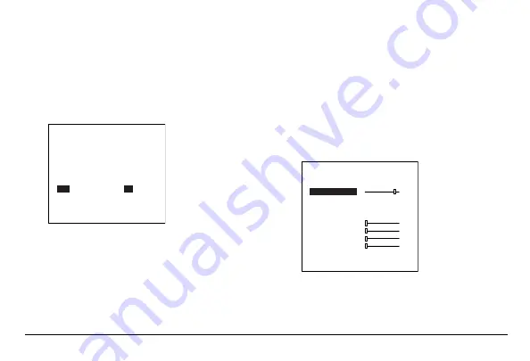
Motion Detection
The motion detection function detects moving objects
in a scene. Motion detection is triggered when the
differences between frames in a monitored area exceed
a specific level.
1.
Press
SET
to display the Setup menu.
2.
Move the cursor to
MOTION DET
, and then
press the left or right setup button to set the
motion detection function.
SETUP MENU
AUTO
LENS
SHUTTER/AGC
AUTO
WHITE BAL
ATW
BACKLIGHT
OFF
PICT ADJUST
ATR
ON
MOTION DET
OFF
NEXT
EXIT
SAVE ALL
MOTION DET
DETECT SENSE
BLOCK DISP OFF
MONITOR AREA ON
AREA SEL 1/4
TOP
BOTTOM
LEFT
RIGHT
RETURN
111
000
000
000
000
Summary of Contents for HCCM674M
Page 31: ......