Connecting Telephone Service
Connecting Incoming Phone Lines
1. Trim back the PVC jacket on the incoming phone
cable approximately ¾-inch (be sure to re-label if
necessary) allowing for a bend radius of at least
four times the diameter of the CAT5 telephone
cable.
2. Separate the pairs from each other but do not
untwist the pairs. Be sure to label each
connection on the provided documentation
template painted on the face of the module.
Note:
Do not untwist the conductors more than ½-inch from
the point of termination.
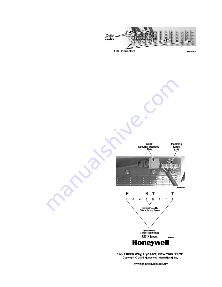
3. Following the 568A color code that is printed on
the 110 connectors, punch down the incoming
cables on the module’s 110 connectors. Start with
the blue pair punch the cable down into the slots.
4. Punch down all the Cat5e cables in the same
fashion, positioning and trimming each in order to
maintain neatness.
Note:
Make sure that the Tip and Ring are properly
connected to the 110 punch down. In most cases the
blue/white is first and then the white/blue.
5. Once the remaining cables have been connected
(up to four lines) the incoming phone lines will be
distributed to the outlet ports on the top side of
the module.
Connecting outgoing telephone cables
The outgoing RJ45 ports will accept cables with either
RJ45 or RJ11 connectors. RJ45 termination is
recommended so that the four line capability can be
used. When terminating the cables follow the 568A
standard.
If a MDP3 patch module is being installed, connect a
patch cord between the telephone outputs and the
zones on the MDP3 patch module.
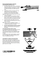
Connecting the module to a Security System
After phone service has been connected to the
module, route a CAT5 patch cord between the RJ31x
port and the security system. Cut the RJ45 connector
off at the Security system end and use the following
diagram to connect the phone service to the security
system and to the module.
‡CSHBT083PV1aŠ
CSHBT083PV1 12/04 Rev. A


